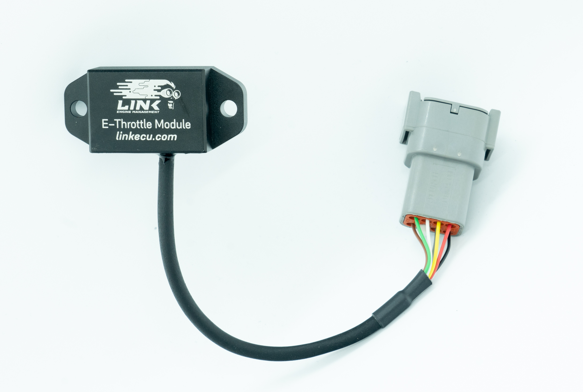
The external electronic throttle control module can be wired as in output interface for ECUs that do not support electronic throttle control internally.
The module requires three auxiliary outputs from the ECU. Signals '1' and '2' control the output drive signals from the module and 'Enable' signal disconnects power from the internal electronic throttle drive.
·Signal 1 must be connected to the first Auxiliary in the selected pair.
·Signal 2 must be connected to the second Auxiliary in the selected pair.
·Enable must be connected to the selected E-Throttle Relay Auxiliary.
The power for the device needs to come from the main relay. Power should ONLY be present at key on.
WARNING
DO NOT POWER THE DEVICE OFF +12V DIRECTLY FROM THE BATTERY. POWER MUST BE SUPPLIED VIA THE MAIN RELAY

External EThrottle Wiring Example
An LED on the end of the case provides information on it's current state:
·A green LED indicates the device is powered and enabled.
·A red LED indicates that there is a fault. A fault condition can occur from an output short circuit, excessive current draw or if the device goes over its rated temperate.
·If the LED is off the device is either not powered or not enabled.
Newer Link E-Throttle Modules (pictured below) also use the same wire colour codes but don't have a status LED.

Link External EThrottle Controller


