


Note: At present no G4X ECUs come with built in Peak and Hold capability.
Measuring Injector Impedance
Measuring injector impedance is simple, all you need is a multimeter.
1.Set the multimeter to its resistance setting with the lowest range possible (e.g. 0Ω 100Ω).
2.Measure the resistance of the multimeter leads by connecting the two together, note down this number.
3.Connect the two leads of the multimeter to the two terminals of the injectors. (Make sure the injector terminals are clean). Note the measured resistance.
4.Subtract the lead resistance from the measured resistance. (e.g. 2.01Ω 0.01Ω = 2.00Ω) This number is the injector impedance.
Note, it is good practice to measure all of the injectors. This checks the condition of the solenoid inside the fuel injector. If an injector has been overheated, the measured impedance is generally lower.
High vs. Low Impedance Injectors
Injectors can be classified as either 'high' or 'low' impedance. As a general rule, 6Ω or greater is considered a high impedance injector, and less than 6Ω is considered low impedance. Low impedance injectors will draw higher current.
Injector Wiring
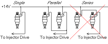
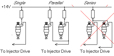
Injectors can be wired either individually or in groups to an injection drive. When wiring injectors in groups, they MUST be connected in a parallel arrangement. Never wire fuel injectors in series.
It is important to consider drive current when wiring injectors. Drive current is the amount of current flowing into any individual injection channel on the ECU.
·When wiring one injector per injection channel, drive current is exactly equal to injector current.
·When wiring multiple injectors per injection channel, drive current equals the sum of the injector currents on that channel.
It is important that the injectors are supplied from the same voltage supply that is used by the ECU. This allows the ECU to accurately measure the injector voltage for dead time correction as well as flywheeling the current when operating in peak and hold mode.
Example
Three 12Ω fuel injectors are wired to an injection channel, the battery voltage is 13.5V.
How much current will each injector draw?
Max Injection Current = Battery Voltage / Injector Impedance
= 13 . 5V / 12Ω
= 1.125 A
How much current will flow into the injection channel (drive current)?
Drive Current = Injector 1 Current + Injector 2 Current + Injector 3 Current +
= 1.125 + 1.125 + 1.125
= 3.375 A
Injection Control Modes
There are two main ways of controlling fuel injectors: saturated control and peak and hold control. Saturated mode is typically suited to driving high impedance injectors and peak and hold mode is suited for driving low impedance injectors.
Note: At present no G4X ECUs come with built in Peak and Hold capability.
·High Impedance Injectors - Saturated Control
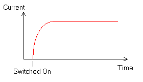
Injector Impedance The injector impedance measured in ohms(Ω) defines the maximum current that will be drawn with an applied voltage. The maximum current can be simply calculated using the following formula: Maximum Injection Current = Battery Voltage / Injector Impedance The term 'Impedance' is used rather than 'Resistance' when talking about fuel injectors. This is due to the inductive properties of the fuel injector. The inductive properties of the fuel injector cause the current to increase in a 'damped' fashion towards it's maximum current.
Example A 12Ω fuel injector is wired to an injection channel, the battery voltage is 13.5V. How much current will the injector draw? Using the above equation - Max Injection Current = Battery Voltage / Injector Impedance = 14V / 12Ω = 1.17 A Example A 3Ω fuel injector is wired to an injection channel, the battery voltage is 14V. How much current will the injector draw? Max Injection Current = Battery Voltage / Injector Impedance = 14V / 3Ω = 4.67 A (very high)
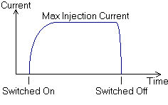
Saturated Control Saturated control is the most simple form of injector control. Basically the injector drive is turned hard on the entire duration of the injection event. This means the maximum current is held for most of the injection period (less the turn-on and turn-off current transitions).
It is critical to not exceed the rated saturated injection current for the ECUs injector drives. |
·Low Impedance Injectors - Peak and Hold
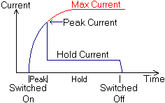
Peak and Hold Control Note: At present no G4X ECUs come with built in Peak and Hold capability. Peak and hold injector control is a two stage system for driving low impedance injectors. Peak and hold provides the advantages of fast opening times (dead time) compared with ballast resistors and low power consumption when holding the injectors open. During the peak stage, the injector drive turns hard on and the current rises towards the maximum injection current. The ECU detects when the current reaches the defined 'Peak Current', at this point the control switches to hold mode. Once in the hold stage, the ECU is acting as an ultra efficient ballast resistor limiting the current through the injector.
You can see from the above image, the maximum current is higher than that of the peak current. If this wasn't the case, the current would never reach its peak value and switch over to hold mode. When setting the peak and hold currents, it is important to consider this. Careful reading of the fuel injector specification sheet will provide minimum opening currents and impedance for calculating the maximum current. Typically the hold current will be one quarter of the peak current. The following table shows typical peak and hold settings.
Ballast Resistors Ballast resistors provide a way of limiting the current through a low impedance fuel injector. A ballast resistor is always wired in series with a fuel injector. Each fuel injector requires it's own ballast resistor. You can not share a ballast resistor over multiple injectors, this will cause varying injection current depending on how many drives are turned on.
Calculating injection current through fuel injectors wired with ballast resistors can be done simply by adding the ballast resistor resistance (Ω) to the injector impedance (Ω). The new impedance can then be used in the previously discussed equations. Effective Injector Impedance = Injector Impedance + Ballast Resistance Maximum Injection Current = Battery Voltage / Effective Injector Impedance
Example Two 2Ω fuel injectors are wired to an injection channel each with a 4.7Ω ballast resistor, the battery voltage is 12V. What is the effective impedance of each fuel injector? Effective Injector Impedance = Injector Impedance + Ballast Resistance = 2Ω + 4.7Ω = 6.7Ω
How much current will each injector draw? Max Injection Current = Battery Voltage / Effective Injector Impedance = 12V / 6.7Ω = 1.79 A
How much current will flow into the injection channel (drive current)? Drive Current = Injector 1 Current + Injector 2 Current + Injector 3 Current + = 1.79 + 1.79 = 3.58A
When selecting a ballast resistor, it is important to select a value that will limit the current enough not to damage the ECU, but supply enough current to open the injector. The alternative to using a ballast resistor is to use a peak and hold control mode, this will be explained further in a following section.
|
Summary
In summary:
·Injectors must never be wired in series.
·If ballast resistors are required, they must be wired per injector.