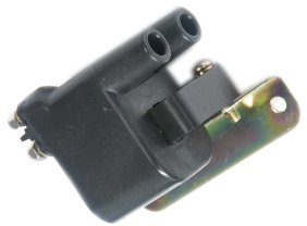
Wasted spark will fire two cylinders simultaneously, using a common dual post coil. When a dual post coil is fired, two cylinders receive a spark. One cylinder is fired conventionally on the compression stroke while the other cylinder has its piston in the same position but on the exhaust stroke. One crankshaft rotation later, these two cylinders are two working stokes further ahead and the spark plugs fire again, but now with reversed roles. The result is that each coil will be fired twice per engine cycle hence the term “wasted spark”. This set-up can ONLY be used on engines with an even number of cylinders.
Dual Post Coils
One dual post coil (with a primary resistance between 0.4 and 1.0 ohms) is required per 2 cylinders. Figure 8.8 shows a typical coil. The coils should be positioned so they minimise the length of the HT Leads. This will help reduce the electrical noise generated when the spark plugs are fired.

Dual Post Coil
The main concern when using dual post coils is the generation of electrical interference. This can interfere with ECU operation and cause unwanted static on car radios. The ignition suppression techniques outlined earlier are particularly important. All wasted spark systems should use ‘Resistive Spark Plugs’ if the engine does not currently use them.
One igniter channel is required for each dual post coil.
Single Post Coils
It is possible to run an engine that has a single coil per cylinder in wasted spark configuration. This is often done when there is not enough ignition drives to control each coil individually. In this case two coils are fired at the same time.
Each coil must be wired to a single igniter channel. It will be necessary to split the wiring from the each ECU ignition output to go to the input of two igniter channels.
IMPORTANT! |
When running a wasted spark arrangement with a single coil per cylinder, each coil must be wired to an individual igniter channel. DO NOT wire the output of one igniter channel to two coils. This will result in very low spark energy and erratic engine running. |
Wasted Spark Ignition Wiring
To ensure each ignition drive is matched to the correct cylinder, the firing sequence will need to be determined. Note this option is only possible when the engine has an even number of cylinders. When using a wasted spark arrangement, an ignition drive will fire cylinder pairs that are 360° apart in the firing order.
·Ignition Drive 1 always needs to be connected to cylinder number 1 and its corresponding cylinder (360° apart in the firing order).
·Ignition Drive 2 should be connected to the next cylinder in the firing order and its corresponding cylinder (360° apart in the firing order).
·If more cylinders exist (6, 8, 10 & 12 cylinder engines) then the pattern should be continued. For example Ignition Drive 3 fires the third cylinder in the firing order and its corresponding cylinder.
Use the following table to determine coil ignition wiring for wasted spark applications. Write the engines firing order in the column on the left.
Write Firing Order Below |
Number of Cylinders |
|||
|---|---|---|---|---|
2 |
4 |
6 |
8 |
|
1 |
Ign 1 |
Ign 1 |
Ign 1 |
Ign 1 |
|
Ign 2 |
Ign 2 |
Ign 2 |
Ign 2 |
|
|
Ign 1 |
Ign 3 |
Ign 3 |
|
|
Ign 2 |
Ign 1 |
Ign 4 |
|
|
|
Ign 2 |
Ign 1 |
|
|
|
Ign 3 |
Ign 2 |
|
|
|
|
Ign 3 |
|
|
|
|
Ign 4 |
Wasted spark Ignition Wiring
Example - Wasted spark set-up for a 4 cylinder engine with 1-3-4-2 firing order.
·Ignition Drive 1 fires cylinders 1 and 4
·Ignition Drive 2 fires cylinders 2 and 3
Example - Wasted spark set-up for a 6 cylinder engine with 1-5-3-6-2-4 firing order.
·Ignition Drive 1 fires cylinders 1 and 6
·Ignition Drive 2 fires cylinders 5 and 2
·Ignition Drive 3 fires cylinders 3 and 4


