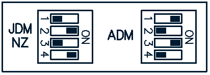
Some models are wired with their trigger (engine position) signals wired in opposite polarity to other models. To allow for this four dip switches have been provided on the ECU.
Set the DIP switches according to the diagram below:
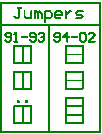
If your ECU bottom board is version 1.2 or higher, you will have a second set of jumpers. The jumpers are used to configure the board for either a 1991 - 1993 or a 1994 - 2002 SR20DET.
Warning: Confirm the vehicles pinout against the information provided in the rear of this manual before configuring and installing the ECU.
|
The rectangles represent the orientation of the jumpers.
·For a 1991 - 1993 SR20DET use six jumpers in the vertical direction as indicated in the diagram. Notice the two dots, no jumper will be fitted here. WARNING - Read the Known Issues section of this manual for information when fitting the ECU to this vehicle model.
·For a 1994 - 2002 SR20DET use seven jumpers in the horizontal direction as indicated in the diagram. There are no spare pins, the jumpers will cover all pins. |
|
Jumper J8 can be fitted to provide a pull-up resistor on the AFM signal. This allows a temperature sensor to be wired to the AFM signal wire. The AFM signal is connected to An Volt 4. If a temp sensor is wired to the AFM signal wire, fit the jumper and set the function of An Volt 4 to IAT-Ext Pull-up. |