


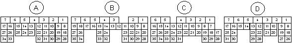
The following pin diagram is provided as a support reference. Please contact your nearest Link dealer for specific pin information.
2004 - 2006 ECU Function |
|||||
Pin |
ECU Pin |
Function |
Pin |
ECU Pin |
Function |
A1 |
DI 4 |
Clutch Switch |
C3 |
Injector 4 |
Injection |
A2 |
nc |
|
C4 |
Injector 3 |
Injection |
A3 |
nc |
|
C5 |
Injector 2 |
Injection |
A4 |
nc |
|
C6 |
Injector 1 |
Injection |
A5 |
nc |
|
C7 |
DI10 |
|
A6 |
Ground |
|
C8 |
nc (Brake NO) |
|
A7 |
nc |
|
C9 |
DI 5 |
Brake Switch (NC) |
A8 |
Aux 8 |
Tumble Valves Close |
C10 |
DI 6 |
Cruise Cancel OR Resume |
A9 |
Linked to A10 |
TGV wired in series |
C11 |
DI 7 |
Cruise Set OR Cancel |
A10 |
Linked to A9 |
C12 |
An Temp 3 |
Fuel Temperature |
|
A11 |
Aux 7 |
Tumble Valves Open |
C13 |
An Temp 2 |
IAT from MAF |
A12 |
nc |
|
C14 |
An Temp 1 |
ECT |
A13 |
nc |
|
C15 |
+5V Out |
|
A14 |
Injector 5 (Aux) |
Purge Solenoid |
C16 |
+5V Out |
|
A15 |
Injector 6 (Aux) |
Cruise Light |
C17 |
An Volt 10 |
APS (Main) |
A16 |
nc (Cruise Set Light) |
|
C18 |
An Volt 2 |
TPS (Main) |
A17 |
Injector 8 (Aux) |
CE Light |
C19 |
nc |
|
A18 |
+14V Out |
AVCS Solenoid |
C20 |
nc |
|
A19 |
+14V Out |
AVCS Solenoid |
C21 |
nc |
|
A20 |
nc |
|
C22 |
An Volt 1 |
MAP |
A21 |
nc |
|
C23 |
An Volt 8 |
MAF Signal |
A22 |
nc |
|
C24 |
nc |
|
A23 |
Aux 3 |
Tacho |
C25 |
Knock 1 |
Knock |
A24 |
nc |
|
C26 |
An Volt 4 |
Left TGV Position |
A25 |
Ground |
|
C27 |
An Volt 5 |
Right TGV Position |
A26 |
nc |
|
C28 |
An Volt 9 |
APS (Sub) |
A27 |
nc |
|
C29 |
An Volt 3 |
TPS (Sub) |
A28 |
Aux 2 |
Bank 1 (RH) AVCS Solenoid |
C30 |
nc |
|
A29 |
Aux 1 |
Bank 2 (LH) AVCS Solenoid |
C31 |
Ground (AFM) |
|
A30 |
nc |
|
C32 |
Ground (AFM Shield) |
|
A31 |
nc |
|
C33 |
Ground (Knock Shield) |
|
A32 |
Aux 5 |
Wastegate Solenoid |
C34 |
Ground (APS) |
|
A33 |
nc |
|
C35 |
Ground (Signal) |
|
A34 |
Ground (Signal) |
|
|
||
|
D1 |
Ground (Signal) |
|
||
B1 |
Ground |
|
D2 |
Ground (Signal) |
|
B2 |
Injector 7 (Aux) |
Rear Oxy Heater |
D3 |
Ground |
|
B3 |
nc |
|
D4 |
Aux 9 |
EThrottle Motor + |
B4 |
Ground |
|
D5 |
Aux 10 |
EThrottle Motor - |
B5 |
+14V Main Relay |
ECU Power |
D6 |
+14V EThrottle |
From EThrottle Relay |
B6 |
+14V Main Relay |
ECU Power |
D7 |
Ground |
|
B7 |
nc |
|
D8 |
DI 8 |
Start Signal |
B8 |
Trig 2 |
Bank 2 (LH) Cam Position |
D9 |
DI 9 |
Neutral Signal |
B9 |
DI 2 |
Bank 1 (RH) Cam Position |
D10 |
An Volt 6 |
Power Steer Switch |
B10 |
Trig 1 |
Trig 1 (Crank) |
D11 |
nc |
|
B11 |
nc |
|
D12 |
nc |
|
B12 |
Ground |
|
D13 |
nc |
|
B13 |
nc |
|
D14 |
Ignition Switch (05-06) |
Controls Main Relay (05-06) |
B14 |
nc |
|
D15 |
Ignition Switch (04) |
Controls Main Relay (04) |
B15 |
Ignition 4 |
Ignition |
D16 |
DI3 (04) / Main Relay (05-06) |
AC Request (04) / Ground when on (05-06) |
B16 |
Ignition 3 |
Ignition |
D17 |
Main Relay (04) / DI3 (05-06) |
Ground when on (04) / AC Request (05-06) |
B17 |
Ignition 2 |
Ignition |
D18 |
nc |
|
B18 |
Ignition 1 |
Ignition |
D19 |
nc |
|
B19 |
nc |
|
D20 |
nc |
|
B20 |
nc |
|
D21 |
nc |
|
B21 |
nc |
|
D22 |
nc |
|
B22 |
Ground (Cams) |
|
D23 |
nc |
|
B23 |
nc |
|
D24 |
nc |
|
B24 |
Ignition 5 (Aux) |
AC Fan |
D25 |
An Volt 7 |
Rear Oxy Signal |
B25 |
Ignition 7 (Aux) |
Engine Fan |
D26 |
nc |
|
B26 |
Aux 6 (04) / DI 1 (05-06) |
FP Speed (04) / Vehicle Speed (05-06) |
D27 |
nc |
|
B27 |
DI 1 (04) / Aux 6 (05-06) |
Vehicle Speed (04) / FP Speed (05-06) |
D28 |
nc |
|
B28 |
nc |
|
D29 |
nc |
|
B29 |
nc |
|
D30 |
nc |
|
B30 |
nc |
|
D31 |
Ground (Shield) |
|
B31 |
Ground (Crank Shield) |
|
Expansion 1 |
Ground (Signal) |
|
B32 |
nc |
|
Expansion 2 |
+5V Out |
|
B33 |
Ignition 6 (Aux) |
AC Relay |
Expansion 3 |
nc |
|
B34 |
nc |
|
Expansion 4 |
nc |
|
B35 |
Ignition 8 (Aux) |
E-Throttle Relay |
Expansion 5 |
An Volt 12 |
|
|
Expansion 6 |
nc |
|
||
C1 |
nc |
|
Expansion 7 |
An Temp 4 |
|
C2 |
nc |
|
Expansion 8 |
An Volt 11 |
|
2006-2007 ECU Function |
|||||
Pin |
ECU Pin |
Function |
Pin |
ECU Pin |
Function |
A1 |
nc |
|
C3 |
nc (Front O2 Heater) |
|
A2 |
nc |
|
C4 |
Injector 7 (Aux) |
Rear Oxy Heater |
A3 |
nc |
|
C5 |
nc |
|
A4 |
nc |
|
C6 |
Ground (Shield) |
|
A5 |
Ground |
|
C7 |
nc |
|
A6 |
An Volt 1 |
MAP (Factory) |
C8 |
nc |
|
A7 |
+14V Main Relay |
ECU Power |
C9 |
Ignition 6 (Aux) |
AC Relay |
A8 |
nc |
|
C10 |
nc |
|
A9 |
nc |
|
C11 |
Injector 8 (Aux) |
CE Light |
A10 |
nc |
C12 |
nc (06) / Aux 6 (07) |
FP Speed (07) |
|
A11 |
DI 2 |
Bank 1 (RH) Cam Position |
C13 |
DI 1 |
Vehicle Speed |
A12 |
nc |
|
C14 |
nc |
|
A13 |
Trig 1 |
Trig 1 (Crank) |
C15 |
Ground (Signal) |
|
A14 |
Ground (Crank) |
|
C16 |
nc |
|
A15 |
Knock 1 |
Knock |
C17 |
nc |
|
A16 |
An Volt 4 |
Left TGV Position |
C18 |
Ignition 7 (Aux) |
Engine Fan |
A17 |
nc |
|
C19 |
nc |
|
A18 |
An Volt 2 |
TPS (Main) |
C20 |
nc |
|
A19 |
+5V Out |
|
C21 |
Ignition 8 (Aux) |
E-Throttle Relay |
A20 |
nc |
|
C22 |
Aux 3 |
Tacho |
A21 |
Trig 2 |
Bank 2 (LH) Cam Position |
C23 |
DI 3 (06) / Main Relay (07) |
A/C Request (06) / Ground when on (07) |
A22 |
Ground (Cams) |
|
C24 |
Main Relay (06) / DI 3 (07) |
Ground when on (06) / A/C Request (07) |
A23 |
nc |
|
C25 |
DI 4 |
Clutch Switch |
A24 |
Ground (Crank Shield) |
|
C26 |
nc |
|
A25 |
Ground (Knock Shield) |
|
C27 |
CAN 2 High |
|
A26 |
An Volt 5 |
Right TGV Position |
C28 |
nc |
|
A27 |
nc |
|
C29 |
Ignition 5 (Aux) |
AC Fan |
A28 |
An Volt 3 |
TPS (Sub) |
C30 |
nc |
|
A29 |
Ground (Signal) |
|
C31 |
DI 9 |
Neutral Signal |
A30 |
nc |
|
C32 |
DI 8 |
Start Signal |
A31 |
nc |
|
C33 |
nc |
|
A32 |
nc |
|
C34 |
nc |
|
A33 |
An Volt 6 |
Power Steer Switch |
C35 |
CAN 2 Low |
|
A34 |
An Temp 1 |
ECT |
|
||
|
D1 |
Ground |
|
||
B1 |
Ground (O2 Shield) |
|
D2 |
Ground |
|
B2 |
+14V Main Relay |
ECU Power |
D3 |
Ground |
|
B3 |
nc (Cruise Set Light) |
|
D4 |
Aux 9 |
EThrottle Motor + |
B4 |
An Volt 7 |
Rear Oxy Signal |
D5 |
Aux 10 |
EThrottle Motor - |
B5 |
nc (+12V constant) |
|
D6 |
nc |
|
B6 |
Injector 6 (Aux) |
Cruise Light |
D7 |
Ground |
|
B7 |
nc |
|
D8 |
Injector 1 |
Injection |
B8 |
nc (Front O2 Signal -) |
|
D9 |
Injector 2 |
Injection |
B9 |
nc (Front O2 Signal +) |
|
D10 |
Injector 3 |
Injection |
B10 |
nc (Fuel Level Sensor) |
|
D11 |
Injector 4 |
Injection |
B11 |
nc |
|
D12 |
Linked to D23 |
TGV wired in series |
B12 |
DI 10 |
Cruise Main |
D13 |
Aux 8 |
Tumble Valves Close |
B13 |
DI 6 |
Cruise Cancel OR Resume |
D14 |
Aux 1 |
Bank 2 (LH) AVCS Solenoid |
B14 |
nc |
|
D15 |
+14V Out |
AVCS Solenoid |
B15 |
nc |
|
D16 |
Aux 2 |
Bank 1 (RH) AVCS Solenoid |
B16 |
nc |
|
D17 |
+14V Out |
AVCS Solenoid |
B17 |
An Temp 3 |
Fuel Temperature |
D18 |
Ignition 1 |
Ignition |
B18 |
An Temp 2 |
IAT from MAF |
D19 |
Ignition 2 |
Ignition |
B19 |
Ignition Switch |
Controls Main relay |
D20 |
Ignition 3 |
Ignition |
B20 |
DI 5 |
Brake (NC) |
D21 |
Ignition 4 |
Ignition |
B21 |
+5V Out (APS Main) |
|
D22 |
Aux 7 |
Tumble Valves Open |
B22 |
+5V Out (APS Sub) |
|
D23 |
Linked to D12 |
TGV wired in series |
B23 |
An Volt 10 |
APS (Main) |
D24 |
nc |
|
B24 |
DI 7 |
Cruise Set OR Cancel |
D25 |
nc |
|
B25 |
nc |
|
D26 |
Ground |
|
B26 |
An Volt 8 |
MAF Signal |
D27 |
Aux 5 |
Wastegate Solenoid |
B27 |
nc |
|
D28 |
nc |
|
B28 |
nc (brake NO) |
|
D29 |
Injector 5 (aux) |
Purge Solenoid |
B29 |
Ground (APS Main) |
|
D30 |
nc |
|
B30 |
Ground (Signal) |
|
D31 |
nc |
|
B31 |
An Volt 9 |
APS (Sub) |
Expansion 1 |
Ground (Signal) |
|
B32 |
nc (Fuel Tank Pressure) |
|
Expansion 2 |
+5V Out |
|
B33 |
Aux 6 (06) / nc (07) |
FP Speed (06) |
Expansion 3 |
DI 11 |
|
B34 |
Ground (AFM) |
|
Expansion 4 |
Aux13 |
|
B35 |
Ground (AFM Shield) |
|
Expansion 5 |
An Volt 11 |
|
|
Expansion 6 |
Aux 12 |
|
||
C1 |
+14V EThrottle |
From EThrottle Relay |
Expansion 7 |
An Temp 4 |
|
C2 |
nc (Front O2 Heater) |
|
Expansion 8 |
Aux 11 |
|