


Four general purpose timers are provided for making control functions. The timers can be reset and held at zero or reset and left to count again based on the activation state and the polarity settings. Once the adjustable maximum value is reached the timer will stop counting up. Timers can be used as axis parameters for tables and as conditions on general purpose outputs, timer runtime values are available to view in the auxiliary outputs runtime values.
The following should be noted about the general purpose timers:
·The timer resolution is in 0.001 s or 1 ms.
·The maximum count time is 16,000,000s.
For each timer the following settings are available:
·Label - Allows the user to add a label to the timer to indicate what it is used for
·Activation - This selects the input that can be used to reset the timer.
·Max Time - The timer will not count above this value, the timer will stop at this value when it is reached.
·Polarity - Determines when the timer is reset; when the activating condition is off (held at zero while inactive), when the activating condition is on (held at zero while active), or when the activating condition changes state (not held at zero).
Example:
The following example shows how to configure a timer for doing a fixed two second NOS purge when the driver presses a steering wheel button:
1.Activating Condition - Assume a steering wheel mounted button has been wired to Digital Input 3. It is correctly set up so that Digital Input 3 status shows ON when the button is pressed.
2.Timer Setup - Configure the timer as follows. This will result in the timer starting counting when the button is pressed and resetting to zero when the button is released.
·Activation = Digital Input 3
·Max Time = 5.000 s (this setting does not really matter for this situation as long as it is above 2.000 s)
·Polarity = Reset when off. The timer will be reset and held at zero when the driver is not pressing the button.
3.Use the Timer - Assume an Auxiliary Output is wired to the NOS purge solenoid. The output is set to turn on when the timer is "greater than 0 AND less than or equal to 2.000 s". The output settings will be:
·Sw Logic = Cond 1 AND 2
·SwOff Timer = 0.0s
·Parameter 1 = Timer 1
·Cond 1 = >
·Value 1 = 0
·Parameter 2 = Timer 1
·Cond 2 = <=
·Value 2 = 2.000
Note that this example could be expanded further by making the ECU automatically trigger the NOS purge for example when the NOS temperature is high and the vehicle is stationary. To do this the timer would be activated from a source such as a Virtual Auxiliary Output.
Example:
The following example shows how to configure a timer to add additional fuel after the engine has been on boost for ten seconds solid. This is to reduce power and heating after the engine has been running on full power for quite some time.
1.Activating Condition - Virtual Auxiliary Output 3 is configured to turn on when MAP is greater than 120 kPa (ie on when on boost). The Virtual Auxiliary Output status will show ON when the engine is on boost.
2.Timer Setup - Configure the timer as follows. This will result in the timer counting up while the engine is on boost.
·Activation = Virtual Auxiliary Output 3
·Max Time = 15.000 s. Note that this setting will control how far across the fuel trim table the timer will be allowed to go.
·Polarity = Reset when off. The timer will be reset and held at zero when the engine is not on boost.
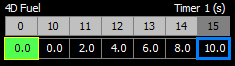
3.Use the Timer - Any of the fuel overlay tables can be used. 4D fuel table is used here. The table could be set up as shown below. The fuel trim will be applied as:
·0% when the timer is between 0 and 10 seconds (ie off boost and for the first ten seconds of boost).
·Between 10 and 15 seconds fuel is progressively increased (2 - 10 %).
·As the timer has a max of 15 seconds, it will stop at 10 % enrichment and stay there until the engine comes off boost.
This example could be extended by also altering the ignition timing or more simply reducing the boost pressure after a time period.