This function allows for electronic boost control on turbo charged engines via a boost control solenoid.
A boost control solenoid is used to modify the pressure signal from the turbocharger compressor outlet to the wastegate actuator. The minimum boost pressure that can be achieved occurs when the solenoid is continuously de-energised (0% Duty Cycle), this pressure is entirely dependent on the wastegate/actuator construction. The maximum boost pressure that can be achieved occurs when the solenoid is continuously energised (100% Duty Cycle), this pressure is typically dependent on the turbocharger/engine combination. Typically this pressure exceeds that which can be safely tolerated by the engine. By varying the on/off ratio (changing the Duty Cycle), a boost pressure between the minimum and maximum can be achieved.
Boost can be controlled using one of two separate strategies; open loop control or closed loop control, the methods of control can be summarized as follows:
Open Loop Control
Open loop control involves applying a duty cycle to the wastegate solenoid based on predefined values and tables. This method of control does not consider the current boost pressure when applying the duty cycle to the wastegate.
More specifically Open Loop Boost Control applies the active Wastegate %DC table value plus the sum of the trim tables when it is active and applies a 0%DC when it is not.
Advantages
The two main advantages to open loop control are inherent stability and simplicity to setup.
Disadvantage
The main disadvantage to open loop control is inconsistency in boost pressure. Boost will change based on several factors including but not limited to barometric pressure, humidity and temperature. These factors will need to be compensated for using tables that modify the duty cycle based on these parameters.
Closed Loop Control
Closed loop control involves applying a duty cycle to the wastegate solenoid based on predefined values, tables and the current boost pressure. This method compares the current boost pressure to the target boost pressure and corrects the duty cycle accordingly to achieve the desired boost.
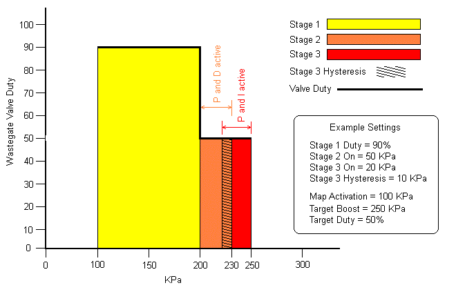
More Specifically operation of the closed loop boost control system has been divided into three separate stages (Stage 1, Stage 2 and Stage 3). Each stage has a specific purpose, and it is important to setup the transition between stages and the control within each stage correctly. Details of each stage are outlined as follows:
Stage 1
Stage 1 is the first stage after closed loop boost control becomes active. Stage 1 applies a fixed duty cycle to the wastegate solenoid, typically 80 - 90%. The purpose of this stage is to spool the turbo as fast as possible by holding the wastegate firmly closed. This stage remains active until Stage 2 becomes active. Please note that when MAP and engine speed (RPM) levels are falling, stage 1 will only re-activate once the MAP or engine speed (RPM) lockout level has been reached.
Stage 2
Stage 2 becomes active once boost pressure comes within a certain range of the target pressure (set using the Stage 2 ON setting). Stage 2 is the first stage of closed loop control. Stage 2 uses proportional and rate of change (P and D) control along with a base duty cycle table. The purpose of this stage is to control the approach to the Boost Target pressure. The duty cycle applied to the wastegate solenoid is the duty cycle from the base table plus the duty cycle from the PD controller. This stage remains active until Stage 3 becomes active.
Stage 3
Stage 3 becomes active once boost pressure comes within a certain range of the target pressure (set using the Stage 3 On setting). Stage 3 is the final stage of closed loop control. Stage 3 uses proportional and offset error (P and I) control along with a fixed base duty cycle. Depending on the Base DC Mode setting, the base duty cycle is either fixed from the final value in Stage 2 or continually updating from the base table. The duty cycle applied to the wastegate solenoid is the base duty cycle plus the duty cycle from the PI controller. This stage remains active until boost pressure is outside its allowed range.

Diagram outlining the three stages of closed loop boost control
Advantage
The main advantage to closed loop control is the boost pressure consistency. With open loop control tables are needed to compensate for changes in environmental conditions. The closed loop system automatically corrects the duty cycle applied to the wastegate solenoid to achieve consistent boost pressures in all conditions.
The Link closed loop boost control strategy also incorporates open loop correction tables in the closed loop control mode. These are provided to help increase control loop stability.
Disadvantage
The main disadvantage to closed loop boost control is the difficulty to setup. Tuning the control loop requires experience and understanding of how the PID control algorithm operates.


