


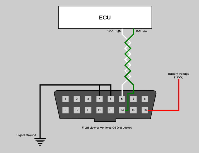
Link G4X ECUs are capable of transmitting live data and fault codes to the vehicles OBD-II port. The ECUs data is transmitted to the ODB-II port over the ECUs CAN bus. The diagram below details the required connections.
OBD-II Pin Connections
Pin |
Function |
Notes |
4 |
Chassis GND |
Connect to ECU Signal GND |
5 |
Signal GND |
Connect to ECU Signal GND |
6 |
CAN High |
Connect to ECU CAN High |
14 |
CAN Low |
Connect to ECU CAN Low |
16 |
Battery Voltage (+) |
Connect to a fused Battery Voltage (12V+) supply |
Install Notes
·Depending on the Link G4X ECU you have the ECU may have one or two CAN bus connections, either CAN bus is suitable for OBD-II communication.
·Depending on the Link G4X ECU you have the CAN bus connections will be onthe main ECU wiring connector, a separate communication port, or may require a 'CANPCB' wiring connector.
·Refer to the CAN Bus Wiring topic for guidelines on the CAN High and CAN Low wiring.
·Refer to the CAN Bus Wiring topic for guidance on wiring multiple CAN devices to the same CAN bus.
·If permanently installing a device to the OBD-II port, an ignition switched power supply to pin 16 is preferable, as this will prevent the device draining the vehicles battery.
·Once the wiring for the OBD-II port is complete refer to OBD (On Board Diagnostics) for setup information.