This setting is used to specify the number of cylinders or rotors that the engine has.
This specifies the engine type, options include:
·2 Stroke
·4 Stroke
·Rotary
The table below summarises the ignition and staged injection systems supported.
Cylinders |
Engine Type |
Ignition Systems Supported |
Staged Injection Systems Supported |
1 |
4 Stroke |
Direct Spark |
Sequential/Group/Sequential Multi-Point |
|
2 Stroke |
Direct Spark |
Sequential/Group/Sequential Multi-Point |
2 |
4 Stroke |
Distributor/Wasted Spark/Direct Spark |
Sequential/Group/Sequential Multi-Point |
|
Rotary |
Leading Wasted/Leading Direct |
Sequential/Group/Sequential Multi-Point |
|
2 Stroke |
Distributor/Wasted Spark/Direct Spark |
Sequential/Group/Sequential Multi-Point |
3 |
4 Stroke |
Distributor/Twin Distributor/Direct Spark |
Sequential/Group/Sequential Multi-Point |
|
Rotary |
Leading Direct |
Sequential/Group/Sequential Multi-Point |
|
2 Stroke |
Distributor/Twin Distributor/Direct Spark |
Sequential/Group/Sequential Multi-Point |
4 |
4 Stroke |
Distributor/Twin Distributor/Wasted Spark/Direct Spark |
Sequential/Group/Sequential Multi-Point |
|
Rotary |
Leading Wasted/Leading Direct |
Sequential/Group/Sequential Multi-Point |
|
2 Stroke |
Distributor/Twin Distributor/Wasted Spark/Direct Spark |
Sequential/Group/Sequential Multi-Point |
5 |
4 Stroke |
Distributor/Twin Distributor/Direct Spark |
Group/Sequential Multi-Point |
6 |
4 Stroke |
Distributor/Twin Distributor/Wasted Spark/Direct Spark |
Group/Sequential Multi-Point |
7 |
4 Stroke |
Distributor/Twin Distributor/Direct Spark |
Group |
8 |
4 Stroke |
Distributor/Twin Distributor/Wasted Spark/Direct Spark |
Group |
9 |
4 Stroke |
Distributor/Twin Distributor |
Group |
10 |
4 Stroke |
Distributor/Twin Distributor/Wasted Spark |
Group |
12 |
4 Stroke |
Distributor/Wasted Spark |
Group |
Note: When running an engine that has regularly spaced TDC points, the Custom TDC Points adjustment should be set to OFF. The majority of engines have regularly spaced TDC points.
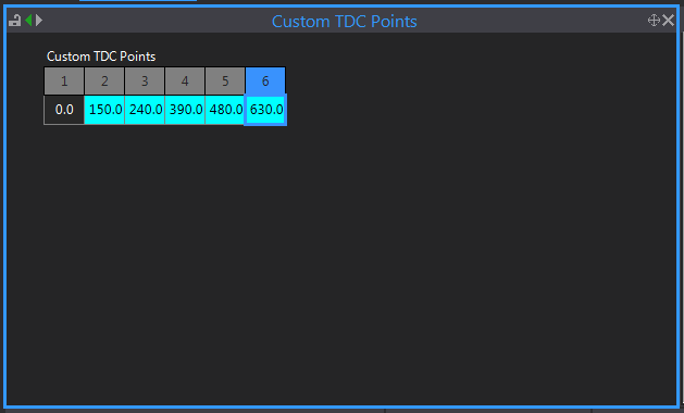
Custom TDC points are used when an engine does not fire at regular intervals such as an odd fire engine. Setting the Custom TDC Points option to On will display the TDC Points Table. The numbers entered in the TDC Points Table correspond to the engine positions of consecutive TDC occurrences. On a four stroke engine these will range from 0 to 720 degrees, whereas a two stroke engine will range from 0 to 360 degrees.
Note: The entries in this table are in the order of the firing order. So, the first entry is the first cylinder in the firing order, the second entry is the second in the firing order etc...
Custom TDC Points for an odd fire six cylinder may look like this:

This is the baud rate at which the RS-232 communications on the ECU will initially start communicating at. PCLink and the ECU perform a handshake at this rate, then ramp up to the rate set in the communications settings. RS-232 devices such as dashes however will continue to communicate at this rate.
Notes:
·The Baud Rate setting will not become effective until the next time the ECUs power is turned on.
·It is recommended that the highest Baud Rate setting is used to improve connection speed to PCLink.
A 20 character text box allowing the user to input a short description of the basemap or engine.
More detailed notes can be entered into the Memo Text found under the 'File' tab or by pressing ctrl + M.
Vehicle Identification Number (VIN)
A 17 character text box allowing the user to input to an identifying code for the vehicle it is being used on.
This selects the firing order of the engine.
This is a field where notes about the base map setup can be entered. The information entered is stored in the ECU.
Examples of use:
·Vehicle owners name
·Engine code
·Vehicle make and model
·Maximum boost level
·Date tuned


