


Fuel Pump Control provides the required functionality to drive various different types of fuel pump speed control configurations.
The following fuel pump and fuel pump speed control configurations are supported:
In all fuel pump speed control modes, the Prime Time setting is available and sets how long the fuel pump will run for when the key is first turned on. A typical value is 3 seconds. As soon as engine speed is detected the fuel pump will run continuously until the engine stops. Prime will be applied at max fuel pump speed in modes that don't contain a Prime Duty Cycle setting.
Modes:
OFF
No Fuel pump Control is performed by the ECU.
This mode requires a Fuel Pump Relay Output to be selected, this output will be turned on for the Prime Time at ECU Power up and then run continuously while the engine is detected to be turning over (running or cranking). This Auxiliary output should be wired to a relay which powers the fuel pump, no other configuration is required.
This type of control is used where two relays (or a control module) are used to switch the fuel pump between two different speeds. The speeds are regulated by the use of current limiting resistors or special circuitry in the control module.
Two Auxiliary Outputs are required to use this mode:
1.Fuel Pump Relay Output should be set to the Auxiliary used to turn the pump on or off (via a relay or control module).
2.Fuel Pump Speed Relay Output should be set to the Auxiliary Output used to switch between high and low speed.
This mode requires the following additional settings to be setup:
·Eng Speed X Over - Sets the Engine Speed that fuel pump speed changes from low to high speed.
·Inj DC X Over - Sets the fuel flow that the fuel pump changes from low to high speed.
When Inj Duty Cycle is greater than Inj DC X Over OR Engine Speed is greater than Eng Speed X Over high speed pump mode is activated. Note that there is a 2% hysteresis on Inj Duty Cycle and a 50RPM hysteresis on engine speed to prevent erratic switching.
This type of control is used where three relays (or a control module) are used to switch the fuel pump between three different speeds. The speeds are regulated by the use of current limiting resistors or special circuitry in the control module.
Three Auxiliary Outputs are required to use this mode:
1.Fuel Pump Relay Output should be set to the Auxiliary used to turn the pump on or off (via a relay or control module).
2.Fuel Pump Speed Relay 1 Output should be set to the Auxiliary Output used to switch between low and medium speed.
3.Fuel Pump Speed Relay 2 Output should be set to the Auxiliary Output used to switch between medium and high speed.
This mode requires the following additional settings to be setup:
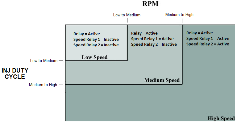
·Low -> Med RPM - Sets the Engine Speed at which the fuel pump speed changes from low to medium speed.
·Low -> Med Duty Cycle - Sets the fuel flow at which the fuel pump changes from low to medium speed.
·Med -> High RPM - Sets the Engine Speed at which the fuel pump speed changes from medium to high speed.
·Med -> High Duty Cycle - Sets the fuel flow at which the fuel pump changes from medium to high speed.
When Engine Speed is greater than Low -> Med RPM OR Inj Duty Cycle is greater than Low -> Med Duty Cycle the output will switch to Medium Speed Mode. Similarly if Medium to High Rpm OR Duty Cycle criteria are met, the output mode will switch to High Speed. Note that there is a 2% hysteresis on Inj Duty Cycle and a 50RPM hysteresis on engine speed to prevent erratic switching.
The board below summarises which output is Active in each specific state:
This type of control uses a Pulse Width Modulated (PWM) signal to a fuel pump speed control module to control the fuel pump speed in three steps. Only one Auxiliary Output is required to use this mode, that Auxiliary Output must be wired to the fuel pump speed control module and selected in Fuel Pump PWM Output.
The control will apply either 33% 66% or 100% duty cycle to the speed control module depending on fuel flow. The following settings are available in this mode:
·PWM Frequency - Output Frequency of the Auxiliary
·Low -> Med RPM - Sets the Engine Speed at which the fuel pump speed changes from low to medium speed.
·Low -> Med Duty Cycle - Sets the fuel flow that the fuel pump changes from low to medium speed.
·Med -> High RPM - Sets the Engine Speed at which the fuel pump speed changes from medium to high speed.
·Med -> High Duty Cycle - Sets the fuel flow that the fuel pump changes from medium to high speed.
When Engine Speed is greater than Low -> Med RPM OR Inj Duty Cycle is greater than Low -> Med Duty Cycle the output will switch to Medium Speed Mode. Similarly if Medium to High Rpm OR Duty Cycle criteria are met, the output mode will to High Speed.Note that there is a 2% hysteresis on Inj Duty Cycle and a 50RPM hysteresis on engine speed to prevent erratic switching.
Actual duty cycle applied to the fuel pump speed controller can be viewed with the 'FP Speed (%DC)' Runtime parameter (found under Auxiliary Outputs Tab).
This type of control uses a Pulse Width Modulated (PWM) signal to a fuel pump speed control module to regulate the fuel pump speed. Only one Auxiliary Output is required to use this mode and that should be selected in Fuel Pump PWM Output. The Auxiliary Output must be wired to the fuel pump speed as usual. Note that a special fuel pump speed control module is required for this type of control. A solid state relay will not be able to switch fast enough for variable speed fuel pump control.
This type of control is normally used on a system with a fuel pressure regulator. The idea is to maintain a constant flow in the fuel return line for all injector flows. Keeping a constant flow through the regulator prevents fuel pressure creep. Reducing fuel pump speed when fuel demand is low also reduces fuel pump current, noise and fuel heating.
The following settings are available for configuring Open Loop Pressure Control:
·Prime Duty Cycle - Sets the duty cycle used during Prime Time.
·PWM Frequency - Output Frequency of the Auxiliary
·Multiplier: Scales the duty cycle to the fuel pump speed control module. For example if 80% FP Speed (%DC) is desired and the pump controller needs 40% duty cycle to run the pump at 80% speed then set Multiplier to 0.5 %/%. If the fuel pump speed control module outputs the same duty cycle as its input then set this number to 1 %/%.
·Offset - Corrects the duty cycle sent to the fuel pump speed control module. This will normally be zero. For example, if the fuel pump speed control module requires a 40% duty cycle input to achieve 50% speed then Offset will be -10%.
·Pump Off DC - The duty cycle that will be applied to the fuel pump speed control module when the engine is not running.
·Min DC Clamp - The minimum duty cycle that will be applied to the fuel pump speed control module. Most pumps will not turn below approx 20% duty cycle. Set this to a value well above the pumps stalling duty cycle.
·Max DC Clamp - The maximum duty cycle that will be applied to the fuel pump speed control module. Note, some modules will go into an error state if a too high duty cycle (eg above 95%) is applied. This setting can also be used to limit max pump speed where an oversized fuel pump is used.
·Fuel Pump Duty Cycle Table - Sets the desired fuel pump speed depending on Inj Duty Cycle. 0% will be pump stopped,100% will be full speed, 50% will be half speed etc. Note, the number in this table is not necessarily the duty cycle applied to the fuel pump speed controller, it is the desired fuel pump speed at a particular Inj Duty Cycle. The actual duty cycle applied to the fuel pump speed controller will depend on the following settings (refer to the equation shown below). The X Axis numbers (injector duty cycle) can be adjusted as required by pressing the X key while on this table.
The duty cycle applied to the fuel pump speed controller is calculated as:
FP Speed (%DC) = FP Speed Table x Multiplier + Offset, clamped between Max DC Clamp and Min DC Clamp
Note the Prime and Pump Off Duty Cycles aren't clamped and don't have the multi or offset applied to them.
This type of control continuously varies a PWM signal to the fuel pump speed control module to regulate measured fuel pressure to a target value. Only one Auxiliary Output is required to use this mode. That Auxiliary Output must be wired to the fuel pump speed control module and configured as FP Speed. An Analog Input must also be wired to a fuel pressure sensor and correctly configured to display calibrated Fuel Pressure.
Note that a special fuel pump speed control module is required for this type of control. A solid state relay will not be able to switch fast enough for variable speed fuel pump control.
Most OEM vehicles that require this type of control have the correct mechanical system to suit it. This type of control does not use a fuel pressure regulator. Only a small bleed is used to keep some fuel circulating in the system. Fuel tank heating is greatly reduced due to reduced fuel circulation and reduced fuel pump current.
To use this mode set Speed Control Method to Closed Loop. The following settings will be available:
·Prime Duty Cycle - Sets the duty cycle used during Prime Time.
·PWM Frequency - Output Frequency of the Auxiliary
·Startup Override Pressure - This pressure is used instead of the Fuel Pressure Target Table during engine starting. It allows removal of air from the system, and is required for correct operation of some GDI high pressure pumps. This pressure target is used when the engine speed is greater than 0 but less than 400rpm.
·Proportional Gain - The proportional gain component in the PID controller.
·Integral Gain - The integral gain component in the PID controller.
·Derivative Gain - The derivative gain component in the PID controller.
·Pump Off DC - The duty cycle that will be applied to the fuel pump speed control module when the engine is not running.
·Min DC Clamp - The minimum duty cycle that will be applied to the fuel pump speed control module while running.
·Max DC Clamp - The maximum duty cycle that will be applied to the fuel pump speed control module while running.
·Fuel Pump Duty Cycle Table - Used as a feed forward value for the PID controller, the value in the table will be used as the base value which the PID adds to or subtracts from. Set this table up so that it controls the fuel pressure as well as possible with no PID Gains and then add the gains to account for changes that this table can't account for.
·Fuel Pressure Target Table - Sets the target fuel pressure for given conditions (typically load and engine speed). Fuel Pressure Target is the interpolated value from this table.
Actual duty cycle applied to the fuel pump speed controller can be viewed by looking at the FP Speed (%DC) runtime value.
Note the Prime and Pump Off Duty Cycles aren't clamped.