Note: Idle offsets and idle up values are not applied cumulatively, the largest offset and the largest idle up that are currently active are applied.
Start-up Corrections
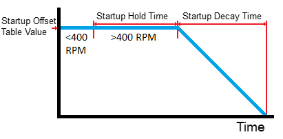
When the engine is started it is often useful to hold the idle slightly higher for a short period of time, this functionality is controlled by these 3 settings:
·Startup Offset Table - Specifies the amount of offset to add to the idle actuator base position during an engine start.
·Startup Hold Time - How long in seconds the start-up idle offset correction is applied following the ecu first seeing engine speed before it starts to decay.
·Startup decay time - The length of time over which the start-up offset will be smoothly removed from the base position until it is completely removed.

Idle Startup Offset
Engine Fan Corrections
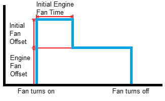
An engine fan turning on can add a noticeable load to an engine that is idling and so it is often preferable to increase the amount of air provided to the engine through the idle actuator when this occurs. Engine fan electrical load usually has a higher initial load while the fan is accelerated from stopped up to speed and a lower draw on the system once it is running at a constant speed, as a result a different initial offset is provided as well as an ongoing offset.
·Engine Fan Offset - Specifies the amount of offset to add to the idle actuator base position while an engine fan is on.
·Engine Fan Initial Offset - Specifies the amount offset to add to the idle actuator position when an engine fan is first turned on. Note that the Engine Fan Offset will also be applied when an engine fan first turns on and so this setting is in addition to that.
·Initial Engine Fan Time - How long in seconds the Engine Fan Initial Offset will be applied for.
·Engine Fan Idle Up - Specifies how much to increase the RPM target by while an engine fan is on. Only used in Closed Loop Idle Speed Control.

Idle Fan offset
Power Steer Corrections
Turning the wheels in a vehicle with power steering adds a noticeable load to an idling engine and so it is often preferable to increase the amount of air provided to the engine through the idle actuator when this occurs.
·Power Steer Offset - Specifies the amount of offset to add to the idle actuator base position while the Power Steer Switch is active.
·Power Steer Idle Up - Specifies how much to increase the RPM target by while the Power Steer Switch is active. Only used in Closed Loop Idle Speed Control.
Gear/Drive Corrections
Being in Gear or in Drive can add extra load to an engine causing a noticeable dip in the idle speed and so it is often preferable to increase the amount of air provided to the engine through the idle actuator when this occurs.
·Gear/Drive Offset - Specifies the amount of offset to add to the idle actuator base position while the Neutral/Park Switch is inactive.
·Gear/Drive Idle Up - Specifies how much to increase the RPM target by while the Neutral/Park Switch is inactive. Only used in Closed Loop Idle Speed Control.
Dashpot Corrections
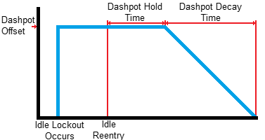
Dashpot is a term for a mechanical damping device. The Dashpot settings in Link ECU's allow a configurable software based damping of the Idle Speed Control to help ensure entry into idle is smooth and controlled. The Dashpot is activated upon entry into idle speed control after having been locked out.
·Dashpot Offset - Specifies the amount of offset to add to the idle actuator base position while the Dashpot is active.
·Dashpot Hold Time - How long in seconds the Dashpot Offset will be applied for before it starts to decay
·Dashpot Decay Time - The length of time over which the Dashpot Offset will be smoothly removed until it is completely removed.

Idle Dashpot
GP Idle Corrections
In some cases an engine load is switched manually by the driver or an external system, GP Idle corrections enable an idle up and offset to be applied when a DI pin becomes active providing better control of the idle speed.
·GP Idle Source - Specifies the input pin being used to control the GP Idle Offset and GP Idle Up.
·GP Idle Offset - Specifies the amount of offset to add to the idle actuator base position while the GP Idle DI is active.
·GP Idle Up - Specifies how much to increase the RPM target by while the GP Idle DI is active. Only used in Closed Loop Idle Speed Control.
Min and Max Clamp
It is often desirable to artificially limit the idle speed actuators range to prevent excessive engine speed or stalling. Some Solenoid type valves don't like being set to the far end of their ranges and so these clamp settings can also help prevent issues arising from this.
·Max Clamp - Specifies the maximum percentage opening that the idle actuator can be set to by the idle speed control functionality. Idle actuator positions higher than the Max Clamp can be set by the antilag isc override functionality and in the event that the idle speed actuator is an ethrottle the Max Clamp can be overridden by the accelerator pedal when idle speed is inactive (in lockout).
·Min Clamp - Specifies the minimum percentage opening that the idle actuator can be set to by the idle speed control functionality. Idle actuator positions lower than the Min Clamp can be set by the antilag isc override functionality and in the event that the idle speed actuator is an ethrottle the Min Clamp can be overridden by the accelerator pedal when idle speed is inactive (in lockout).
AC Correction
Turning the AC Clutch on adds load to the engine which can result in a noticeable dip in the idle speed and so it is often preferable to increase the amount of air provided to the engine through the idle actuator when this occurs.
·AC Offset Table - Specifies the amount of offset to add to the idle actuator base position while the AC Request Switch is active. This is done on the AC Request switch rather than the AC Clutch output as it gives the idle time to ramp up before the AC Clutch kicks in (AC Output has Clutch Delay setting) and because in the majority of cases the AC Clutch will be active at idle when requested.
·AC Idle Up - Specifies how much to increase the RPM target by while the AC Request is active. Only used in Closed Loop Idle Speed Control.
refer to Closed Loop ISC for information on the Deadband and Integral Gain settings.


