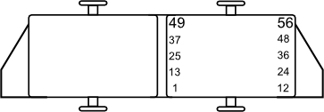
Looking into the ECU side connector
Pin |
ECU Pin |
Function |
Pin |
ECU Pin |
Function |
1 |
nc |
|
36 |
CAN 2 High |
|
2 |
Injector 5 (Aux) |
EFI Relay |
37 |
Aux 5 |
ISC Stepper |
3 |
nc |
|
38 |
Aux 8 |
ISC Stepper |
4 |
Aux 2 |
Engine Fan |
39 |
Trig 1 |
Trig 1 |
5 |
Injector 1 |
Injection |
40 |
nc |
|
6 |
nc |
|
41 |
nc |
|
7 |
+5V Out |
|
42 |
Ground (Signal) |
|
8 |
nc |
|
43 |
nc |
|
9 |
DI 1 |
Ignition Switched 12v+ |
44 |
An Temp 1 |
ECT |
10 |
An Volt 2 |
TPS |
45 |
DI 2 |
Vehicle Speed |
11 |
nc |
|
46 |
nc |
|
12 |
nc |
|
47 |
nc |
|
13 |
nc |
|
48 |
CAN 2 Low |
|
14 |
nc |
|
49 |
nc |
|
15 |
nc |
|
50 |
Ground |
|
16 |
Injector 2 |
Injection |
51 |
Ground |
|
17 |
Injector 6 (Aux) |
AWD Hub Coil |
52 |
Ground |
|
18 |
nc |
|
53 |
+14V |
ECU Power |
19 |
Aux 1 |
Fuel Pump Relay |
54 |
Aux 3 |
|
20 |
nc |
|
55 |
Ign 1 |
|
21 |
nc |
|
56 |
Ign 2 |
|
22 |
An Volt 1 |
Factory MAP signal (Atmospheric pressure only) |
|
||
23 |
An Volt 4 |
Transmission Position Switch |
On Board MAP |
An Volt 3 |
MAP |
24 |
An Temp 2 |
Intake Air Temperature |
Expansion 1 |
CAN1 High |
|
25 |
Aux 6 |
ISC Stepper |
Expansion 2 |
Aux 9 |
|
26 |
Aux 7 |
ISC Stepper |
Expansion 3 |
Aux 4 |
|
27 |
Ground (signal) |
|
Expansion 4 |
Injector 4 (Aux) |
|
28 |
DI 3 |
AWD Switch |
Expansion 5 |
Injector 3 (Aux) |
|
29 |
nc |
|
Expansion 6 |
+5V Out |
|
30 |
Ground (signal) |
|
Expansion 7 |
CAN1 Low |
|
31 |
nc |
|
Expansion 8 |
DI 5 |
|
32 |
DI 4 |
Input for equipment not fitted to all models |
Expansion 9 |
Knock 1 |
|
33 |
nc |
|
Expansion 10 |
An Volt 5 |
|
34 |
nc |
|
Expansion 11 |
An Temp 3 |
|
35 |
nc |
|
Expansion 12 |
Ground (Signal) |
|
Note: Ignition 1&2 have built in igniters, Ignition 3 and onwards do not.
Note: Injector Drives 7 and 8 aren't exposed and don't have the hardware required to drive Injectors.

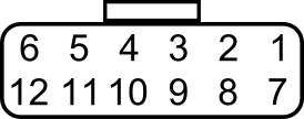
Looking into ECU side connector
Pin Number |
Function |
Notes |
1 |
CAN H |
Communication bus |
2 |
Auxiliary Output 9 |
Maximum current of 2 amps when driving to GND |
3 |
Auxiliary Output 4 |
Maximum current of 2 amps when driving to GND |
4 |
Injector Drive 4 |
Maximum current of 5 amps |
5 |
Injector Drive 3 |
Maximum current of 5 amps |
6 |
+5V |
For sensors only |
7 |
CAN L |
Communication bus |
8 |
Digital Input 5 |
Digital Input |
9 |
Knock 1 |
Knock sensor input |
10 |
AN Volt 5 |
Analog 0-5V input |
11 |
AN Temp 3 |
Temperature Sensor Input |
12 |
Sensor GND |
For sensors only |
Part numbers for expansion connector plug:
·Connector - MX23A12SF1
·Retainer - MA23A12Xf1
·12 x Terminals - M23S05K351.


