


The User CAN Setup form allows configuration of each CAN module. Select PCLink > ECU Controls > CAN Configuration to open the CAN Setup window.
Note: Setting up the CAN bus is an advanced task and should only be done by experienced users. It can be very time consuming and some knowledge of CAN protocols and how computer systems store numerical data is required. It is unlikely that incorrect configuration will cause damage to any devices, however it is possible to interfere with the communication of other working devices.
Warning: Changes made inside this window are not automatically stored. Make sure you click Apply or OK, then do a Store to have the ECU permanently remember the settings.
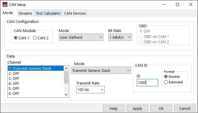
The Mode tab of the CAN Setup window is used to configure the following:
·CAN Configuration
·CAN Module Selection - Determines which CAN Module is being configured. Note that not all Link ECUs have multiple CAN channels.
·Mode - Choose from one of the pre-configured modes to match a certain vehicle or the User Defined mode.
·Bit Rate - Configure the bit rate to suit the CAN bus you are connecting to. Note that all devices on the CAN bus must communicate at the same bit rate.
·OBD - On Board Diagnostics. Choose to have OBD on CAN 1, CAN 2, or OFF. ISO 15764-4 is a standard protocol used for OBD communication. Note: Most OBD scanners and tools will only work at 250 or 500 kbit/s, this means that all devices on the same CAN bus as the OBD tool or scanner must work at the same rate.
·Data - These settings are only adjustable when using User Defined mode.
·CAN Channels - Select the CAN channel you wish to configure.
·Mode - Choose the mode for the selected channel. The possible choices are:
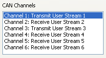
·Transmit User Stream X - Transmit User Stream X from the ECU on the selected channel.
·Receive User Stream X - Receives User Stream X into the ECU on the selected channel.
·Transmit / Receive from built in devices.
·Transmit Rate - The frequency at which the selected channel is transmitted onto the CAN bus. This setting is only accessible when the selected channel is configured to a transmit mode. Be aware that certain devices have a minimum frequency they require. Pre-configured Transmit Modes which require a certain transmit frequency to work correctly will have these pre-set in the ECU firmware, and changing the Transmit Rate will have no effect.
·ID - The ID the selected channel will use. If the channel is on a receive mode the ID needs to match the ID of the CAN frame the sending device sends. If the channel is on a transmit mode the ID needs to match the ID of the CAN frame the receiving unit is expecting. The CAN ID must be greater than zero.
·Format - Choose whether the channel will use Standard or Extended format. A standard frame has an identifier length of 11 bits and an extended frame has an identifier length of 29 bits. Each CAN Module is capable of transmitting and receiving both standard and extended frames at the same time.
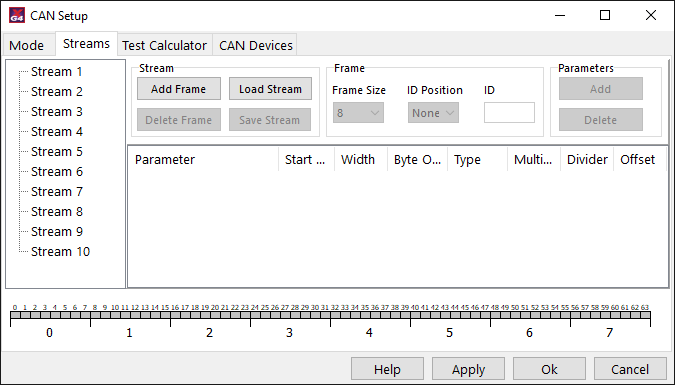
The Streams tab of the CAN Setup window is used to configure the following:
·Streams list - Used to select the stream to be configured.
·Stream - A stream can be a single or multiple CAN frames transmitted or received on a single CAN Id.
·Add Frame - Add a new frame to the stream currently selected in the streams list. The added frame will have a size of eight bytes by default.
·Delete Frame(s) - Delete the frame selected in the streams list. If a Stream is selected in the streams list all its frames will be deleted.
·Load Stream - Load a pre-configured stream into the stream currently selected in the streams list. Note that this will overwrite any frames the selected stream currently has.
·Save Stream - Save the stream currently selected in the streams list to a file for future use.
·Frame - Used to configure the selected frame.
·Frame size - Choose the size of the currently selected frame, the size must be between one and eight bytes. Most applications will use a frame size of eight bytes.
·ID Position - Choose which byte to insert the frame ID into. Most applications will use 'None'.
·ID - Configure the ID number to use for the frame. If 'None' is selected for ID Position then this field will be grayed out.
·Parameters - The data transmitted or received in a particular CAN frame.
·Add - Select a parameter to add to the currently selected frame. Use the Transmit and Receive filters to help sort the parameters.
·Delete - Delete the parameter currently selected.
·Parameter Configuration.
·Parameter - Displays the name of the parameter.
·Start Pos - Configure where in the frame the parameter will start.
·Width - Configure how many bits of the frame the parameter will use.
·Byte Order - Configure whether the Most Significant bit comes first (MS first or Big endian) or the Least Significant bit comes first (LS first or Little endian).
·Type - Configure if the parameter is a signed or unsigned number.
·Multiplier - Multiply the parameter value to make it the same as what the other CAN device(s) require.
·Divider - Divide the parameter value to make it the same as what the other CAN device(s) require.
·Offset - Apply an offset to the parameter value to make it the same as what the other CAN device(s) require.
·Visual Frame Display - Use this to help correctly configure the selected CAN frame.
The Test Calculator tab of the CAN Setup window is used to help setup the CAN bus correctly.
The CAN Devices tab lets the user interface with Link CAN-Lambda modules. Do not cycle power to the ECU while configuring CAN devices. If you do, you may need to exit and re-enter the CAN Setup window to continue.
Use this procedure to configure Link CAN-Lambda module:
1.Connect to the ECU.
2.Navigate to ECU Controls > CAN Setup.
3.In the 'Mode' tab ensure the appropriate CAN Module is selected.
4.In the CAN Configuration box:
1.Set the mode to 'User Defined'.
2.Ensure the Bit Rate is set to '1 Mbit/s'
5.In the Data box:
1.Select a free channel and set its Mode to 'Link CAN-Lambda'.
2.In the CAN ID box, set the ID to 950, leave the format on 'Normal'.
6.Switch to the CAN Devices Tab.
7.Connect a Link CAN-Lambda device to the CAN Bus you selected in step 2.
8.Press the 'Find Devices' button.
9.One or more devices should appear in the list, if they do not go back to one and check your settings, check your CAN Bus and ensure that the device is receiving power.
10.Select the device you wish to change.
All devices are shipped assigned to Lambda 1, this means you will need to attach the device you wish to use for Lambda 1 last.
11.Use the parameter column drop down box to reassign the device.
12.Use the bit rate column to change the devices bit rate.
13.Once you are satisfied with the changes, press the 'Send' button.
14.Cycle power to CAN Lambda Module only - not the ECU (unplug Deutsch connector for example)
1.If you cannot cycle the power to the CAN Lambda Module without also cycling power to the ECU, press the Ok button to close CAN Setup before you cycle ECU power.
15.To add more devices repeat steps 6 to 13.
Notes:
You cannot mix bit rates on the same bus, neither devices will appear when there are devices with mixed bit rates on the same bus.
Modules are shipped configured as Lambda 1, this means that you must assign Lambda 1 last. Do not assign the same parameter to two or more devices. They must be programmed one at a time.
You only need to cycle power to the device(s), you do not have to cycle power to the ECU. For this reason it might be easiest to simply unplug each device as needed.
Setup Instructions:
Configuring a CAN Module to a pre-defined Mode
The pre-defined modes are used by Link G4X Plug-in ECUs. They are also available for wire-in applications in supported vehicles.
Use this procedure to configure the ECUs CAN module to transmit and receive data in a pre-defined Mode.
1.Select the appropriate CAN Module.
2.Select the required mode from the drop down Mode list.
3.Click the Apply button.
4.Click OK to close the CAN Setup window.
5.Don't forget to do a Store (F4 key).
Configuring a CAN Transmit Channel to a pre-defined Mode
Use this procedure to configure the CAN module to transmit pre-configured data to an external device such as a dash.
1.Select the appropriate CAN Module.
2.Select 'User Defined' from the Mode drop down list.
3.Configure the Bit Rate to suit the CAN bus you are connecting to. Note that all devices on the CAN bus must communicate at the same bit rate.
4.Select a spare channel in the CAN Channels list.
5.Select the pre-configured Mode you wish to transmit on the channel.
6.Enter the ID for the CAN Channel. Note that this must match the CAN ID the receiving devices are configured to listen for.
7.Select the Transmit Rate at which you wish to transmit the channel.
8.Continue setting up other channels as required.
9.Click the Apply button to apply the changes.
10.Click the OK button to close the CAN configuration window.
11.Don't forget to do a Store (F4 key).
Configuring a CAN Transmit Channel using a CAN Stream file
Use this procedure when wanting to transmit pre-configured data contained in a CAN Stream file.
1.Select the appropriate CAN Module.
2.Select 'User Defined' from the Mode drop down list.
3.Configure the Bit Rate to suit the CAN bus you are connecting to. Note that all devices on the CAN bus must communicate at the same bit rate.
4.Select a spare channel in the CAN Channels list.
5.Select the next available 'Transmit User Stream X' from the drop down Mode list. A User Stream number can only be used to transmit or receive, it is recommended to have the User Stream Mode number match the Channel number. See the image below for an example.
6.Enter the ID for the CAN Channel. Note that this must match the CAN ID the receiving devices are configured to listen for.
7.Select the Format required. This will need to match the format the receiving devices are configured to.
8.Select the Transmit Rate at which you wish to transmit the channel.
9.Change to the 'Streams' tab of the CAN Setup window.
10.Select the Stream that was chosen in step 5. Click the 'Load Steam' button and select the desired file containing the pre-configured stream data.
11.Continue setting up other channels as required.
12.Click the Apply button to apply the changes.
13.Click the OK button to close the CAN configuration window.
14.Don't forget to do a Store (F4 key).
Configuring a Custom CAN Transmit Channel
Use this procedure to configure a custom CAN Transmit Channel.
1.Select the appropriate CAN Module.
2.Select 'User Defined' from the Mode drop down list.
3.Configure the Bit Rate to suit the CAN bus you are connecting to. Note that all devices on the CAN bus must communicate at the same bit rate.
4.Select a spare channel in the CAN Channels list.
5.Select the next available 'Transmit User Stream X' from the drop down Mode list. A User Stream number can only be used to transmit or receive, it is recommended to have the User Stream Mode number match the Channel number. See the image below for an example.
6.Enter the ID for the CAN Channel. Note that this must match the CAN ID the receiving devices are configured to listen for.
7.Select the Format required. This will need to match the format the receiving devices are configured to.
8.Set the Transmit Rate at which the channels data will be transmitted. Be careful selecting an unnecessarily fast rate. This would cause unnecessary bus load, particularly if the receiving device can not process all the extra information.
9.Change to the 'Streams' tab of the CAN Setup window.
10.Select the Stream that was chosen in step 5. Click the 'Add Frame' button.
11.Click the 'Add' button in the parameters section. Select the Parameter you want to transmit from the list.
12.Configure the Start position, Width, Byte Order, Multiplier, Divider and Offset to match what the receiving devices are expecting. The CAN frame layout diagram is a useful visual aid to help with setup. Setting these up correctly can be quite complex, see the CAN Setup examples for more information.
13.Add more parameters as required.
14.Click the Apply button to apply the changes.
15.Click the OK button to close the CAN configuration window.
16.Don't forget to do a Store (F4 key).
Configuring a CAN Receive Channel to a pre-defined Mode
Use this procedure to configure the CAN module to receive pre-configured data from an external device such as a CAN thermocouple unit.
1.Select the appropriate CAN Module.
2.Select 'User Defined' from the Mode drop down list.
3.Configure the Bit Rate to suit the CAN bus you are connecting to. Note that all devices on the CAN bus must communicate at the same bit rate.
4.Select a spare channel in the CAN Channels list.
5.Select the pre-configured Mode you wish to receive on the channel.
6.Enter the ID for the CAN Channel. Note that this must match the CAN ID the transmitting device is configured to transmit on.
7.Continue setting up other channels as required.
8.Click the Apply button to apply the changes.
9.Click the OK button to close the CAN configuration window.
10.Don't forget to do a Store (F4 key).
Configuring a CAN Receive Channel using a CAN Stream file
Use this procedure when wanting to receive pre-configured data contained in a CAN Stream file.
1.Select the appropriate CAN Module.
2.Select 'User Defined' from the Mode drop down list.
3.Configure the Bit Rate to suit the CAN bus you are connecting to. Note that all devices on the CAN bus must communicate at the same bit rate.
4.Select a spare channel in the CAN Channels list.
5.Select the next available 'Receive User Stream X' from the drop down Mode list. A User Stream number can only be used to transmit or receive, it is recommended to have the User Stream Mode number match the Channel number. See the image below for an example.
6.Enter the ID for the CAN Channel. Note that this must match the CAN ID the transmitting device is configured to transmit on.
7.Select the Format required. This will need to match the format the transmitting device is configured to.
8.Change to the 'Streams' tab of the CAN Setup window.
9.Select the Stream that was chosen in step 5. Click the 'Load Steam' button and select the desired file containing the pre-configured stream data.
10.Continue setting up other channels as required.
11.Click the Apply button to apply the changes.
12.Click the OK button to close the CAN configuration window.
13.Don't forget to do a Store (F4 key).
Configuring a Custom CAN Receive Channel
Use this procedure to configure a custom CAN Receive Channel.
1.Select the appropriate CAN Module.
2.Select 'User Defined' from the Mode drop down list.
3.Configure the Bit Rate to suit the CAN bus you are connecting to. Note that all devices on the CAN bus must communicate at the same bit rate.
4.Select a spare channel in the CAN Channels list.
5.Select the next available 'Receive User Stream X' from the drop down Mode list. A User Stream number can only be used to transmit or receive, it is recommended to have the User Stream Mode number match the Channel number. See the image below for an example.
6.Enter the ID for the CAN Channel. Note that this must match the CAN ID the transmitting device is configured to transmit on.
7.Select the Format required. This will need to match the format the transmitting device is configured to.
8.Change to the 'Streams' tab of the CAN Setup window.
9.Select the Stream that was chosen in step 5. Click the 'Add Frame' button.
10.Click the 'Add' button in the parameters section. Select the Parameter you want to receive from the list. Note that not all parameters are capable of being received, use the filter to see which are.
11.Configure the Start position, Width, Byte Order, Multiplier, Divider and Offset to match what the transmitting device is sending. The CAN frame layout diagram is a useful visual aid to help with setup. Setting these up correctly can be quite complex, see the CAN Setup examples for more information.
12.Add more parameters as required.
13.Click the Apply button to apply the changes.
14.Click the OK button to close the CAN configuration window.
15.Don't forget to do a Store (F4 key).