


Controller Area Network (CAN) is a communications bus protocol designed for multi-device communications in electrically noisy environments. CAN allows many devices to be connected to the same two wire bus. CAN is found in many factory vehicles and is supported by many after market devices such as dash displays. Link G4X ECUs support up to two independent CAN modules.
Note: Link G4X ECUs support a user configurable CAN bus.
Refer to the following topics for configuration of a CAN bus:
·User CAN Setup - for configuring the Link G4X CAN modules.
·Device Specific CAN Information
CAN Bus Basics
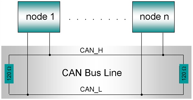
Physically a CAN bus consists of a pair of wires labeled CAN H and CAN L. Each device on the bus "taps" off these two wires. These wires are twisted along their length and terminated at each end with terminating resistors. Twisting and terminating resistors are essential to ensure correct signal integrity on the bus. The following diagram illustrates the minimum CAN bus:
Each device on the bus transmits in units called "Frames". Frames are small messages that have a "CAN Identifier" (CAN ID) and some data. CAN is a broadcast bus. This means that when one device transmits a frame, all other devices can receive that frame. The rule on the bus is that only one device is ever allowed to transmit a particular CAN ID. So as long as no two devices are set up to transmit on the same CAN ID then everyone is happy.
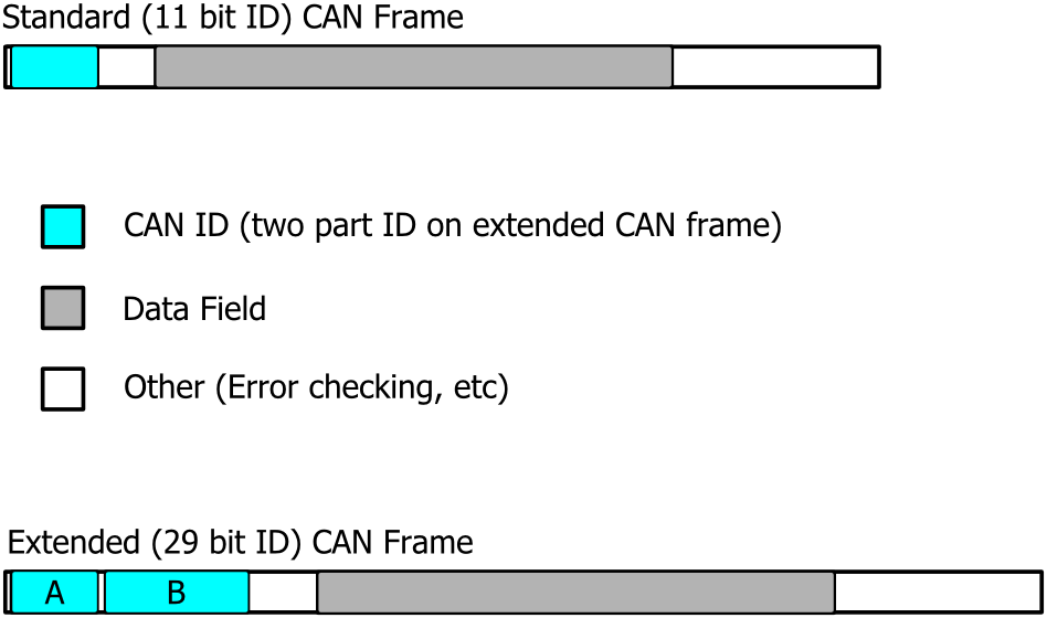
Link G4X ECUs can transmit and receive two different CAN Frame types, these are known as Standard and Extended. The Standard Frame type uses a CAN ID with a length of 11 bits, while the Extended Frame type uses a CAN ID with a length of 29 bits (11bits + 18 bits). The diagram below shows the difference between the two CAN frame types, notice how both Frame types are have the same Data Field length (64 bits).
It is important to understand the difference between bits and bytes. One byte is made up of eight bits. Each bit can have a value of either 0 or 1, this means that one byte can have 256 different combinations of bits. When a value is represented by multiple bytes the number of combinations is multiplied. For example, a two byte number can have 65536 different combinations of bits (256 * 256 = 65536).
The data carried within each CAN frame is the useful part of the frame that allows us to send parameters such as engine speed. Each CAN Frame Data Field can contain data up to 64 bits (or 8 bytes) long.
The data field can contain more than one parameter and lots of frames can be sent one after the other to transmit a longer data stream. The amount of parameters (such as engine speed) that can be sent in one data field depends upon how many bytes each parameter uses
As all devices are on the same CAN bus they must all talk at the same data rate. Most devices have a selectable data rate. Make sure all devices on the bus are set to the same rate (eg 1MBps).
To get data from one device to another, you must define the CAN ID that the sending device will transmit its data on. Then the receiving device must be configured to listen for that CAN ID and use the data appropriately. It is not always possible to configure both the transmitting and receiving devices. Usually one device has a fixed setup (usually the receiver) and the transmitter must be configured as specified by the receivers manufacturer.
For more in depth information search Controller Area Network on the internet or refer to CAN on Wikipedia.
Installation and Wiring
Custom wiring of a CAN bus requires advanced knowledge of communications wiring techniques. It is recommended to use plug in wiring solutions where they are available. Refer to the G4X Wiring and Installation Manual for further information on ECU wiring. Also refer to each of the CAN devices installation manuals.