


Auxiliary Outputs can be wired in a variety of different ways depending on the function they are used for. It is essential that an output is wired correctly to ensure correct operation.
Technical Terms used on this page:
·Load - Any solenoid, relay or device driven from an auxiliary output.
·Low Resistance Load - Typically less than about 100 Ohms.
·High Resistance Load - Typically much greater than 100 Ohms.
·Low Side Driver - A transistor that can join the auxiliary output to ground.
·High Side Driver - A transistor that can join the auxiliary output to the power supply.
This page provides information on the following Auxiliary Output wiring methods:
·Low Side Driving Low Resistance Loads
·Low Side Driving High Resistance Loads
·High Side Driving Low Resistance Loads
And the most important topic:
AVOIDING AUXILIARY OUTPUT BACK-FEEDING
Low Side Driving Low Resistance Loads
This is the most commonly used method of driving loads. Most solenoids used in engine management are Low Side driven (also referred to as "Switched to Ground"). When wired this way, one terminal of the load is connected to a power supply and the other to an ECU auxiliary output. The output turns on and grounds the load though the ECU. Fuel Injectors, relays, control solenoids, VVT solenoids, ISC solenoids and 6 terminal steppers and oxygen sensor heaters are usually wired this way. The following diagram shows a low side driver turned ON. Note that in the ON state the auxiliary output pin is at 0V. When the driver is turned OFF no current flows through the load and the Auxiliary output pin is at 14V. This is referred to as Low Polarity. Warning/shift lights are often wired in this way.
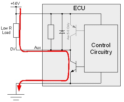
Low Side Driving a Low Resistance Load (Low Polarity, Drive ON)
Low Side Driving High Resistance Loads
This wiring method is usually only used when wiring an auxiliary output to drive another controller. Although the load is not technically being 'low side driven' only a low side driver is used. This wiring method is typical for integrated fuel pump speed controllers and engine fan speed controllers. The following diagram shows the auxiliary output turned on to drive the external controller. Note that when the controller is turned on the auxiliary output pin is pulled up by the ECUs pull-up resister to a high voltage of about 5 to 14 V. This is referred to as High Polarity.
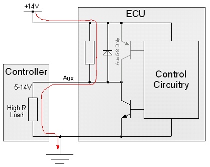
Low Side Driving a High Resistance Load (High Polarity, Drive ON)
To turn the controller off, the auxiliary outputs low side driver is activated driving the auxiliary output pin voltage to 0 as shown in the diagram below.
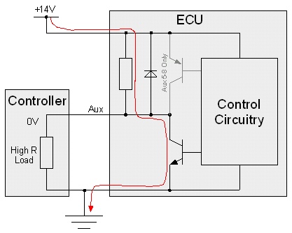
Low Side Driving a High Resistance Load (High Polarity, Drive OFF)
Auxiliary outputs may be connected to a high intensity LED to provide a shift, or warning light. However, a 1kΩ (1000Ω) current limiting resistor is required to be placed in series with the LED. Failure to install the resistor will result in permanent failure of the LED. A bulb may also be used instead of an LED (and it does not require a resistor).

Connection of an LED to an Auxiliary Output
To switch any large load through a relay, the wiring shown below should be used. Examples of such loads include fuel pumps, engine coolant fans and air conditioning compressor clutches. DO NOT wire high current devices directly to the ECU.

Switching Loads Using a Relay
High Side Driving Low Resistance Loads
Sometimes a load can not be wired with one of its terminals to a power supply. These loads are typically single wire solenoids that are grounded through the engine block such as a Honda VTEC control solenoid. In this case it is necessary to supply power to the solenoid from the ECU. This is referred to as High Side driving the solenoid.
The following important points apply to high side driving a solenoid:
·Only a low resistance solenoid can be high side driven.
·Only Auxiliary Outputs 5 to 8 can high side drive loads.
·Aux 5 to 8 high side drivers can supply up to 0.5 Amps, this means the solenoid must have a resistance greater than 30 Ohms.
When wiring solenoids to be high side driven, set the Auxiliary Outputs Drive Mode to High Side. The following diagram shows a high side driven Auxiliary Output turned on. Note that when the Auxiliary Output is turned ON the Auxiliary Output pin has been driven high to 14V.
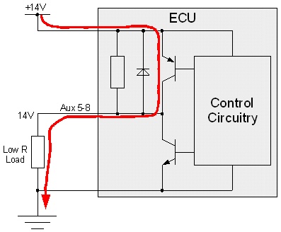
High Side Driving Low Resistance Load (Drive ON)
To see why a high resistance load can not be wired to be high side driven, refer to the following diagram. The pull-up resistor is always present so even when the high side driver is OFF, there is still a small current flowing through the load. In a low resistance solenoid this current will not usually be enough to energise the solenoid enough to turn it on. If a high resistance load was wired, it would never turn off.
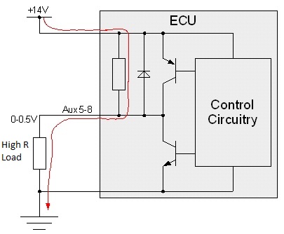
High Side Driving Low Resistance Load (Drive OFF)
Push-Pull driving refers to wiring a load in such a was as that when the outputs are in one state current flows in one direction through the load (push), and when the drivers are in the opposite state the current flows in the other direction through the load (pull). The loads two terminals are wired to auxiliary outputs 5 and 6 or 7 and 8. This drive mode is only used to control four terminal ISC stepper motors and bidirectional DC motors. There are no configurable auxiliary outputs options when using a push-pull drive mode. Wire as per given wiring diagrams and select the correct auxiliary output function.
Avoiding Auxiliary Output Back-feeding
A large number of technical support requests are received regarding problems due to incorrect wiring of auxiliary outputs. Incorrect wiring of solenoids and relays to auxiliary outputs can result in the following symptoms:
·ECU not powering down when the key is turned off.
·Accessories such as engine fans coming on when the key is turned off.
·Repeated clicking of relays when the key is turned off (machine gun sound!).
·ECU draining the battery over a few days.
The root cause of these problems is the wiring of hot fed (direct from the battery positive terminal) or ACC fed (key in accessory position) solenoids or relays to ECU auxiliary outputs.
Each auxiliary output consists of a low side driver and flywheeling diode. A low side driver is a power transistor that can switch a load to ground. Flywheeling diodes are required for the driving of fast switching devices such as ISC solenoids and VVT solenoids. Flywheeling diodes are also essential for reducing radio interference noise.
Unfortunately, the placement of flywheeling diodes means that if power is applied to auxiliary outputs through a solenoid or relay when the ECU is powered down current will flow through the flywheeling diode causing the ECU to power back up.
As solenoids have some resistance, the current that flows back into the ECU (back feeds) is not usually enough to power the ECU up properly resulting in the ECU powering up and down continuously. This causes unusual behavior by the offending solenoid and possibly other solenoids as its current is switched on and off.
The diagrams below show the effect of wiring a solenoid to an auxiliary output that has its power supply wired directly to the battery. The top diagram shows the ignition switch on, the ECU powered up properly and the auxiliary output switched on. Current is being driven through the low side driver to ground and everything works as expected.
The lower diagram shows the ignition switch turned off. Note the current flow through the solenoid, into the ECU, through the flywheeling diode and back on to the ECUs power supply. This would cause the ECU to remain powered up after the ignition switch is turned off. How well it stays powered up depends on how low the resistance of the solenoid is.
Both of these diagrams show INCORRECT wiring...
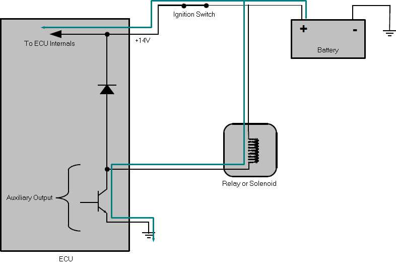
Incorrect Auxiliary Wiring with Key On
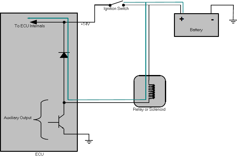
Incorrect Auxiliary Wiring with Key Off
The diagrams below show the correct wiring of solenoids. Note that the power supply to the solenoid is disconnected when the ignition switch is turned off. This diagram shows how solenoids are wired in most vehicles. The relay would typically be the EFI main relay.
Both of these diagrams show CORRECT wiring...

Correct Auxiliary Wiring with Key On

Correct Auxiliary Wiring with Key Off
Other notes:
·This does not apply to Auxiliary Ignition or Auxiliary Injection outputs as they do not have flywheeling diodes fitted. For that reason solenoids that require flywheeling can not be wired to these drives without an external flywheeling diode fitted. This will only usually apply to ISC solenoids.
·This problem will not occur on loads wired to be High Side driven.
·Engine fan relays are often fed from the ACC circuit. These should be wired to non flywheeled outputs such as Ignition or Injection channels. Alternatively their power supply should be changed to one that is disconnected when the ignition switch is turned off.
·Most Nissan ISC solenoids are hot fed (Battery +14V).