


Engine Protection features are offered to reduce the risk of engine damage due to unexpected circumstances. The following conditions will invoke limits:
·RPM Limit - Prevents engine RPM increasing beyond a specified value.
·MAP Limit - Prevents manifold pressure from exceeding a specified value.
·GP RPM Limit - Use configurable 3D tables for engine RPM limiting.
·Speed Limit - Prevents vehicle speed from exceeding a specified value.
·System Voltage Limit - Shuts down the ECU if system voltage exceeds a specified value.
A general description of the Limiting System used in Link G4X ECUs is given HERE.
This function limits the engine speed (RPM) to a safe level, the limiting is performed by interrupting fuel injection and ignition events. Note that it is still possible to exceed the rpm limit during down shifts or deceleration.
The RPM Limit uses the settings described in the Limiting System page and has additional Dual Table settings which are described below.
·Dual Tables - turns dual tables on or off, when using dual tables two rpm limit tables are allocated and the user can switch between them with a DI or virtual Aux.
·Dual Limit Activation - Allows the user to select the DI or virtual Aux that when active will cause the second table to become Active and the 1st table to become inactive.
·RPM Limit Table - The table of Values that the RPM is to be limited to.
·RPM Limit Table 2 - The table of Values that the RPM is to be limited to when dual tables is on and the dual limit activation is active.
This function limits the Manifold Absolute Pressure (MAP) to a defined level, this is used to prevent the boost pressure exceeding a safe level on turbo charged/supercharged engines. Under normal conditions with a correctly operating boost control system the MAP Limit should never be reached. Note that the MAP Limit does not directly control manifold pressure but uses Fuel and/or Ignition cuts are used to reduce it.
The MAP Limit uses the settings described in the Limiting System page and has additional Dual Table settings which are described below.
·Dual Tables - turns dual tables on or off, when using dual tables two map limit tables are allocated and the user can switch between them with a DI or virtual Aux.
·Dual Limit Activation - Allows the user to select the DI or virtual Aux that when active will cause the second table to become Active and the 1st table to become inactive.
·MAP Limit Table - The table of Values that the MAP is to be limited to.
·MAP Limit Table 2 - The table of Values that the MAP is to be limited to when dual tables is on and the dual limit activation is active.
The GP RPM Limits provide the user additional configurable RPM limits which provides the tuner with the ability to specify an RPM limit based on some internal or external conditions not covered by the standard RPM Limit.
The GP RPM Limits use the settings described in the Limiting System page and have additional lockout and delay settings which are described below.
·Startup Lockout - The time in seconds that the GP RPM Limit conditions will not be checked operating after the engine is started, this allows the user to have a limit that isn't applied until after the engine has completed startup.
·Activation Delay - The time in seconds that the limit conditions are active for before the limit will be applied, the time starts from when engine speed exceeds the value specified in the GP RPM Limit table.
·GP RPM 1&2 Limit Table - The table of Values that the RPM is to be limited to.
Example: To setup a RPM Limit based on engine oil pressure:
1.Wire an oil pressure sensor to an analog channel, set the Oil Pressure Source as that analog channel and correctly specify the sensor calibration.
2.Turn on the GP RPM Limit by setting the mode to the desired cut method.
3.Set the Startup Lockout setting to a suitable value e.g. 10 seconds, this means that the engine will be allowed to run for 10 seconds after startup for stable oil pressure to be achieved.
4.Set the Activation Delay to a suitable value e.g. 3 seconds. This means the engine could have an oil pressure fluctuation lasting for up to three seconds before the limit will be invoked. This is useful for near stall situations where low engine speed causes the oil pressure to momentarily dip.
5.Set one axis of the GP RPM Limit Table to the Oil Pressure Runtime and set the other axis to a suitable parameter such as engine speed.
6.Fill in the table values, an example table is shown below.
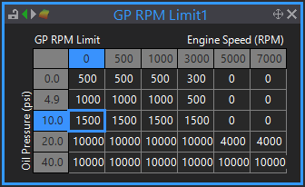
Explanation of table numbers:
·At 0 PSI oil pressure, the engine speed will not be allowed to exceed 500 RPM. This will not take effect until 10 seconds after the car has started. So if there is no pressure at all after 10 seconds the engine will be limited to 500 RPM.
·At anything less than 20 PSI oil pressure, the engine speed will be limited to somewhere between 500 and 1500 RPM depending on the actual engine speed and oil pressure, this allows the engine to still run but not rev as there is some but not enough oil pressure.
·At anything above 40 PSI oil pressure the engine speed is allowed to rev through to 10000 RPM. Note that the main RPM Limit will most likely limit the engine before this. The point is that with a very high number in the table the GP RPM Limit will not activate before other limits.
·If oil pressure fails and drops below 20 PSI when the engine is doing high RPM, the engine will be limited to 0 RPM. This will cause the engine to slow until it reaches idle where it will then be limited at 500 RPM. Note that the oil pressure must have to fail for at least 3 seconds (Activation Delay time) before the engine will be limited.
An alternative would be to use throttle position on the X axis and not let the engine run with open throttle if oil pressure is low. Note that it may be desirable to have 0 RPM in the 0 PSI row to cause the engine to be stalled if oil pressure fails.
This limit is designed to limit the maximum vehicle speed. If the vehicle speed limit is reached the ECU will invoke fuel and/or ignition cuts to reduce power. A vehicle speed sensor must be installed and correctly configured for this function to work. See Speed Sources for details.
The following adjustments are available to specifically configure the Speed Limit:
·Speed Source - Driving or Driven speed.
·Speed Limit Switch - Selects a control to turn the Speed Limit on and off, this can be used to implement a pit lane speed limit. Set the function to Always On to have the Speed Limit always activate when speed exceeds the limit value.
·Speed Limit - The actual vehicle speed at which the limit will be invoked when the Speed Limit Switch is active.
·Speed Limit Switch 2 - Selects a control to turn the second Speed Limit on and off, this can be used to implement a second speed limit that can be turned on and off.
·Speed Limit 2 - The actual vehicle speed at which the limit will be invoked when the Speed Limit Switch 2 is active.
Note: If both speed limits are active the vehicle speed will be limited to the lower of the two speeds specified.
Speed Limit Example
If you want to set a pit-lane speed limiter up to limit the vehicle speed to 60km/h, you might do the following:
·Set the Speed Limit to 60km/h
·Set the appropriate ON/OFF Control channel
·Test and tweak to ensure the settings in Advanced Mode if necessary so that the limit is aggressive enough to hold the speed under 60kph, while not being so aggressive that it results in massive surges in speed.
This is designed to protect the Link ECU and other electronics in the event of a faulty charging system or incorrect jump starting. If the system voltage exceeds the Shut Down Voltage, the ECU will stall the engine.