


The following controls relate to the ignition setup. Typically these will be set once during the initial setup procedure and left unaltered after that.
The correct Ignition Mode must be selected which corresponds to the type of ignition system being used.
The following options are available:
·Off
Ignition is disabled (use for fuel only applications or diagnostics), no Ignition Drives are used.
·Distributor
A single coil is used with a distributor, wire Ignition Drive 1 to the coil.
·Twin Distributor
This uses two ignition coils and two distributors e.g. some Toyota/Lexus V8 engines. The ECU alternates between firing Ignition Drive 1 and Ignition Drive 2, wire Ignition 1 to the coil connected to the Distributor connected to cylinder 1 and Ignition 2 to the other.
Example: Toyota 1UZFE Non VVT, firing order of 1-8-4-3-6-5-7-2 with one distributor connected to cylinders 1,4,6&7 and the other connected to cylinders 8,3,5&2.
When taking into account the order of the leads coming out of the distributors and the positions of the rotor caps this setup will result in:
Ignition Drive 1 firing while connected to cylinder 1
Ignition Drive 2 firing while connected to cylinder 8
Ignition Drive 1 firing while connected to cylinder 4
Ignition Drive 2 firing while connected to cylinder 3
Ignition Drive 1 firing while connected to cylinder 6
Ignition Drive 2 firing while connected to cylinder 5
Ignition Drive 1 firing while connected to cylinder 7
Ignition Drive 2 firing while connected to cylinder 2
·Wasted-spark
This ignition type uses dual-post coils with each coil firing the spark plugs of two cylinders. This mode will use half as many Ignition Drives as there are cylinders, pair cylinders that half an engine cycle apart with each other. Each Ignition Drive can either be wired up to a two post coil with leads running from that coil to the pair of cylinders or to two separate coils connected to the pair of cylinders. Note if using 2 coils per Ignition Drive and external igniters you will need to wire the Ignition Drive into two igniter channels with the corresponding igniter outputs going to one of the coils each (never wire one igniter output to two coils).
Example: Toyota 1UZFE Non VVT, firing order of 1-8-4-3-6-5-7-2, this engine using Wasted-Spark would require 4 Ignition Drives (as it is an 8cyl engine) and they would be wired as shown below:
Ignition Drive 1 connected to cylinders 1 and 6
Ignition Drive 2 connected to cylinders 8 and 5
Ignition Drive 3 connected to cylinders 4 and 7
Ignition Drive 4 connected to cylinders 3 and 2
·Direct Spark
Each cylinder has its own ignition coil. This mode uses the same number of Ignition Drives as cylinders, wire each Ignition Drive to the cylinder of the same number (Ignition Drive 1 to cylinder 1, Ignition Drive 2 to cylinder 2 etc).
·Rotary - Leading Wasted
For rotary engines with one dual post coil for both leading spark plugs. This mode requires 3 Ignition Drives for every 2 rotors and can't be used on engines with an odd number of rotors (e.g. 20B engines).
Wire the Ignition Drives as shown below:
2 Rotor |
Ignition Drive 1 |
Rotor 1&2 Leading |
Ignition Drive 2 |
Rotor 1 Trailing |
|
Ignition Drive 3 |
Rotor 2 Trailing |
|
4 Rotor |
Ignition Drive 1 |
Rotor 1&2 Leading |
Ignition Drive 2 |
Rotor 3&4 Leading |
|
Ignition Drive 3 |
Rotor 1 Trailing |
|
Ignition Drive 4 |
Rotor 2 Trailing |
|
Ignition Drive 5 |
Rotor 3 Trailing |
|
Ignition Drive 6 |
Rotor 4 Trailing |
Note when using an RX7 plugin you typically require a trigger offset of 180 due to differences in how the leading and trailing ignition drives are allocated compared to G4+
·Rotary - Leading Direct
For rotary engines with a separate coil for each leading spark plug. This mode requires 2 Ignition Drives per rotor.
Wire the Ignition Drives as shown below:
1 Rotor |
Ignition Drive 1 |
Rotor 1 Leading |
Ignition Drive 2 |
Rotor 1 Trailing |
|
2 Rotor |
Ignition Drive 1 |
Rotor 1 Leading |
Ignition Drive 2 |
Rotor 2 Leading |
|
Ignition Drive 3 |
Rotor 1 Trailing |
|
Ignition Drive 4 |
Rotor 2 Trailing |
|
3 Rotor |
Ignition Drive 1 |
Rotor 1 Leading |
Ignition Drive 2 |
Rotor 2 Leading |
|
Ignition Drive 3 |
Rotor 3 Leading |
|
Ignition Drive 4 |
Rotor 1 Trailing |
|
Ignition Drive 5 |
Rotor 2 Trailing |
|
Ignition Drive 6 |
Rotor 3 Trailing |
|
4 Rotor |
Ignition Drive 1 |
Rotor 1 Leading |
Ignition Drive 2 |
Rotor 2 Leading |
|
Ignition Drive 3 |
Rotor 3 Leading |
|
Ignition Drive 4 |
Rotor 4 Leading |
|
Ignition Drive 5 |
Rotor 1 Trailing |
|
Ignition Drive 6 |
Rotor 2 Trailing |
|
Ignition Drive 7 |
Rotor 3 Trailing |
|
Ignition Drive 8 |
Rotor 4 Trailing |
Note when changing from Leading waste to leading direct the ignition drives will need to be rewired and the trigger offset will need to be re-calibrated.
Spark Edge sets the edge of the ignition signal that causes the coil to fire a spark. The following options are available:
·Falling - The coil charging will start when the ignition signal goes high and fire the spark when the signal goes back low (FALLS from high to low) . On an oscilloscope this signal would be normally low with a high pulse equal to the length of the current dwell time.
·Rising - The coil charging will start when the ignition signal goes low and fire the spark when the signal goes back high (RISES from low to high). On an oscilloscope this signal would be normally high with a low pulse equal to the length of the current dwell time.
Do not confuse the Spark Edge setting with the trigger falling/rising edge settings. The Trigger Edge settings have NO effect on the ignition output signals polarity.
Note: For almost all applications, this setting will be Falling. Rising is used for some Honda, Ford and MSD ignitions.
The complete electronic circuit used for ignition timing includes many delays. Signals must go through edge detection, filtering, microprocessor, ignition output circuitry, igniter circuitry and finally the coil. Each element introduces a small but significant delay (20 to 200 microseconds). In fact even the timing light used to view ignition angle has a built in delay. These delays are inherent in ALL engine managements systems and components.
At low engine speeds the time between ignition firing events is large and the effects of delays are minimal. As engine speed increases the effects of delays becomes more of a problem ultimately resulting in a slight timing retard (usually only a few degrees). This retard can be easily seen by locking the ignition timing to a constant value and increasing RPM. This effect is often referred to as reluctor retard.
The Ignition Delay setting provides compensation to offset circuit delays eliminating timing retard.
The Ignition Delay setting is not designed to correct for other problems that may effect timing stability such as mechanical shifting of trigger sensor pickup wheels (due to cam belt stretch etc...).
Setting Ignition Delay
IMPORTANT
Setting up the ignition delay requires the engine speed to be increased from cranking speed to peak engine speed. For this reason it is recommended to have the tuning of the base map at a point where the tuner is confident it is safe. Failure to ensure the base map tune is in a safe state could lead to engine damage.
To setup the Ignition Delay perform the following steps:
1.Make sure the ECU is online with PCLink.
2.Open the 'Set Base Timing' window under ECU Settings > Triggers > Calibrate
3.Set the Ignition Delay to 0 microseconds (remembering to press enter after changing the value).
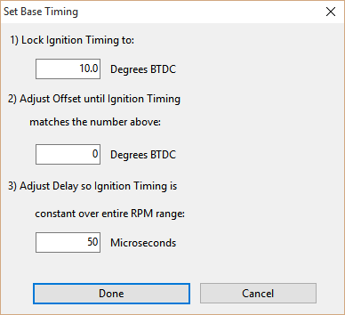
1.Using a good quality timing light, increase the engine speed and watch the timing mark to see if it retards as the engine speed increases .
2.Increase the Ignition Delay and then increase the engine speed and recheck the timing mark. Repeat the process until the retard is eliminated across the entire engine speed range.
Most ignition systems require an Ignition Delay value of 40 to 80 microseconds.
In most distributor ignition systems it is not possible to maintain full dwell time at high engine speeds as there is simply not enough time between spark events. In these applications the dwell must be automatically decreased at high rpm. Of the total time between spark events there is the dwell time (where the coil is charging) and the Spark Duration (while the spark plug is actually being fired). If dwell begins before the spark has finished then the spark is extinguished too early. Therefore there must be a minimum time to elapse before the ECU will begin dwell time. This value has been called Minimum Spark Duration and is typically between 0.5 - 1.0ms.
Maximum Advance specifies the maximum Ignition Angle advance that will ever be applied to the engine. This avoids the case where various ignition trim values and the Ignition Table value accumulate to a dangerously high advanced Ignition Angle, it also helps prevent damage occurring if an excessively high advance value is inadvertently entered in the Ignition Table.
Note: Maximum Advance does not invoke any physical engine cuts, it simply limits maximum Ignition Angle advance to the preset value.
This function allows ignition wiring to be tested. Each ignition channel can be tested individually. This function will only operate when engine speed is 0 RPM. When a particular ignition channel's Ignition Test function is turned ON, the ignition channel will be pulsed at 10 Hz with a pulse width (dwell time) of 5 ms.