


Note: Refer to the Engine Specific Information section for suggested settings for specific engines. A lot of common engines have their own entry in the Trigger Modes list.
There are a large number of triggering variants used by different engine manufacturers. The important differences are the type of sensors used, the number of pulses sent from the sensor during the engine cycle and the timing of the pulses.
The Trigger Mode tells the ECU the number of pulses and the timing of these pulses in relation to each other (the trigger pattern that the engine uses).
Link ECUs use digital trigger decoding so that the actual trigger pattern may be selected (via the Triggering Mode) and processed by the Link ECU.
Important Note: Check all other trigger settings after changing Trigger Mode as changing the Trigger Mode will change other trigger setup information. All trigger parameters are re-initialised to pre-selected values each time Trigger Mode is changed. After selecting the desired Trigger Mode, other triggering parameters can then be adjusted as required. Most importantly, check the Trigger Offset value as this will change the base timing.
Contact your nearest Link Dealer if you are at all unsure of what to select for Trigger Mode.
Note: When the Trigger Mode is set to Multi-tooth it is recommend to have the Trigger 2 tooth edge a reasonable distance from any of the trigger 1 teeth, this is to help prevent the trig 2 tooth crossing over a trigger 1 tooth which can occur on engines with trigger wheels located in separate locations. If the trigger 2 tooth does cross over a trig 1 tooth the ECU will lose sync which can cause the engine to misfire or stop. It does not matter which trigger 1 teeth edges the trigger 2 tooth edge falls between.
Note: When the Trigger Mode is set to Multi-tooth / Missing it is recommended to have the trigger 2 tooth edge a reasonable from the Trigger 1 'Sync Tooth' as the trigger 2 tooth crossing over the sync tooth can cause it to sync incorrectly when starting. When using a VVT cam signal for Trigger 2 ensure that none of the teeth on any of the VVT cams can cross over the Trigger 1 sync tooth.
For information on specific trigger modes, click Here.
The RPM Filtering setting helps stabilise the Engine Speed parameter. It does this by averaging the number of Top Dead Centre (TDC) readings. On some engines (usually 1 or 2 cylinder engines) the engine speed rapidly accelerates and de-accelerates, causing the Engine Speed parameter to fluctuate rapidly, this can make it very hard to tune the engine. By averaging the TDC points the Engine Speed parameter reads much more consistently, making it easier to tune the engine.
·1 - Default - This is the default setting and should be used for nearly all engines, the exception is one and two cylinder engines where the engine speed is fluctuating rapidly.
·2 - The Engine Speed parameter will be averaged over two TDC points.
·3 - The Engine Speed parameter will be averaged over three TDC points.
·4 - The Engine Speed parameter will be averaged over four TDC points.
Select the correct type of trigger sensor connected to this trigger input. Options are:
·Reluctor - For variable reluctance type sensors. Characterised by the use of spiked trigger wheels and usually only two wires.
·Opto/Hall - For Optical or Hall Effect type sensors. Characterised by the use of slotted discs or rotors and typically three wires.
Warning: This is an advanced feature and should only be configured by a trained tuner.
Trigger Filtering sets the amount of hardware filtering applied to trigger input signals.
Some trigger signals contain a large amount of high frequency interference and electrical noise. This interference can cause false trigger events to occur. Filtering is used to eliminate this interference. Ideally the least amount of filtering required should be used.
Note: This option is only available when using Optical/Hall Trigger Type.
Trigger Pull-up enables the pull-up resistor on a trigger input. Pull-up resistors are often required for open collector (switch to ground) optical and hall effect sensors.
Most optical and hall effect sensors will require the pull-up resistor to be ON.
If 'Piggy-backing' a factory ECU, make sure pull-ups are turned off, as the factory ECU will be providing the pull-up.
For further information on the purpose of pull-up resistors, click HERE.
Note: This option is only available when using Optical/Hall Trigger Type.
Select the edge of the trigger signal that indicates the trigger event:
·Rising - The trigger event occurs when the signal goes from a low voltage (eg 0V) to a high voltage (eg 5,8 or 12V).
·Falling - The trigger event occurs when the signal goes from a high voltage (eg 5,8 or 12V) to a low voltage (eg 0V).
·All - The trigger event occurs when the signal goes from a high voltage to a low voltage and also occurs when the signal goes from a low voltage to a high voltage.
Select the driving source of the multi tooth crank angle sensor. Options are Cam or Crank.
This value specifies the total number of symmetrical teeth or slots in the multi-tooth trigger wheel.
Warning - A valid tooth count must divide evenly into 360. Typically most trigger wheels will be fine with the exception of 32. (360 / 32 = 11.25). This situation will cause uneven timing between cylinders.
Note: Where a trigger wheel has teeth missing, this value must be set to the number of teeth that would of been counted if the teeth were not missing.
Note: The maximum number of teeth selectable in PCLink when using Multi-tooth or Multi-tooth / Missing is 200.
Example:
If a trigger wheel has 24 symmetrically spaced teeth, set this value to 24.
Example:
When using a trigger wheel with 58 teeth and a gap where two teeth are missing (i.e. there would be sixty teeth if it was not missing), set the Tooth Count value to 60 and Missing Teeth value to 2. Note that this is generally known as a "60 minus 2" trigger wheel.
Note: This option is only available when using Multi Tooth/Missing Trigger Mode.
This value specifies the number of teeth or slots that are missing from the trigger wheel.
Example:
When using a trigger wheel with 58 teeth and a gap where two teeth are missing (ie there would be sixty teeth if they were not missing), set the Tooth Count value to 60 and Missing Teeth value to 2. This is generally known as a "60 minus 2" trigger wheel.
This value specifies the number of locations in which there are missing teeth, these locations have to be evenly spaced and all have the same number of missing teeth. The number of teeth missing per gap is set by the Missing Teeth Setting above.
This setting specify's the tooth on the crank trigger that is used for synchronising the cams. The value is the number of teeth after the sync point to the Sync Tooth. For Multi-Tooth mode the sync point is trigger 2 tooth, for MultiTooth/Missing the sync point is the gap. For example a value of 3 when using MultiTooth/Missing means the 3rd tooth after the gap is the tooth being used for synchronising the cams.
The only restriction on the tooth used is that none of the cam teeth can cross this tooth during their vvt swing, each cam tooth must always be on one side or the other of the sync tooth for the full cam movement. For example if using a Multi-Tooth pattern with a trigger sync on one cam and a vvt signal on the other this setting needs to be set to a trigger 1 tooth that none of the vvt teeth cross over the full cam swing.
Refer to CAM Pulse Window below for a better explanation and diagram.
Note: This setting is only visible in MultiTooth / Missing Mode.
Note: This option is only available when using a Reluctor Trigger Type.
Warning: This is an advanced feature and should only be configured by a trained tuner.
The Trigger Arming Threshold Table sets the voltage required to 'Arm' the trigger generation circuitry before waiting for a falling edge.
The purpose of the trigger arming circuitry is to improve the trigger inputs ability to reject interference and electrical noise, thus helping to eliminate spurious trigger signals. At low engine speeds (particularly when cranking), reluctor sensors produce a very low voltage signal. Therefore at low RPM a lower arming voltage is required. As engine speed increases so does the amplitude of the reluctor sensors signal. This allows higher arming thresholds to be used. Different arming voltages can be entered for each 1000 RPM.
Specifies the way in which the trigger system will synchronize. This setting can be found under ECU Settings > Triggers > Trigger 2. This setting is only visible in certain trigger modes.
The following options are available:
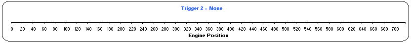
·None
The engine will not sync to the 720 degree engine cycle. This sync mode will NOT work with multi-tooth Trigger Mode, but WILL work with multi-tooth / missing Trigger Mode.
Trigger 1 - Multi-tooth / Missing |
|
Trigger 2 Sync Mode - None |
|
Supported engine configurations |
Rotary, 2 Stroke, 4 Stroke (with group fuel modes and distributed or wasted spark ignition modes) |
Notes |
With this trigger setup the ECU knows the engine position within a 360 degree engine cycle. |
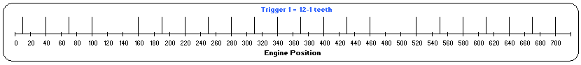
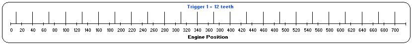
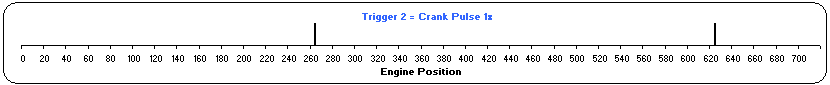
·Crank Pulse 1x
The sync will be an edge off a crank sensor. The engine will sync to 360 degrees within an engine cycle and would be used for a 2 stroke or rotary engine.
Trigger 1 - Multi-tooth |
|
Trigger 2 Sync Mode - Crank Pulse 1x |
|
Supported engine configurations |
Rotary, 2 Stroke, 4 Stroke (with group fuel modes and distributed or wasted spark ignition modes) |
Notes |
With this trigger setup the ECU knows the engine position within a 360 degree engine cycle. |
Trigger 1 - Multi-tooth / Missing |
|
Trigger 2 Sync Mode - Crank Pulse 1x |
|
Supported engine configurations |
Rotary, 2 Stroke, 4 Stroke (with group fuel modes and distributed or wasted spark ignition modes) |
Notes |
With this trigger setup the ECU knows the engine position within a 360 degree engine cycle. Using the Crank Pulse 1x sync mode with multi-tooth / missing trigger mode provides no benefit over having the sync mode set to None. |
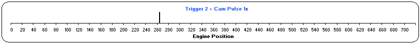
·Cam Pulse 1x
The sync will be an edge off a cam sensor. The engine will sync to the 720 degree engine cycle. The cam trigger wheel has one tooth that the ECU uses in conjunction with the crank trigger to determine engine position.
Trigger 1 - Multi-tooth |
|
Trigger 2 Sync Mode - Cam Pulse 1x |
|
Supported engine configurations |
4 Stroke (with sequential or group fuel modes and distributed, wasted spark, or direct spark ignition modes) |
Notes |
With this trigger setup the ECU knows the engine position within a 720 degree engine cycle. The trigger 2 tooth has to remain between the same two Trigger 1 teeth. |
Trigger 1 - Multi-tooth / Missing |
|
Trigger 2 Sync Mode - Cam Pulse 1x |
|
Supported engine configurations |
4 Stroke (with sequential or group fuel modes and distributed, wasted spark, or direct spark ignition modes) |
Notes |
With this trigger setup the ECU knows the engine position within a 720 degree engine cycle. The trigger 2 tooth can move across Trigger 1 teeth but cannot at any point be located in the Trigger 1 gap. |
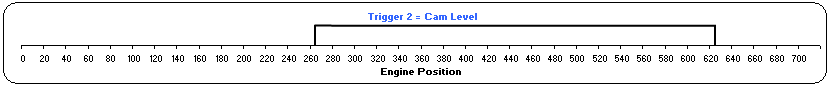
·Cam Level
The sync will be a level on the cam. The engine will sync to the 720 degree engine cycle. Because the crank trigger rotates at twice the rate of the cam trigger, the ECU will know engine position by monitoring if the cam signal is high or low. This sync mode will NOT work with multi-tooth Trigger Mode, but WILL work with multi-tooth / missing Trigger Mode.

Cam Level wheel

Cam signal from cam level wheel.
Trigger 1 - Multi-tooth |
|
Trigger 2 Sync Mode - Cam Level |
|
Supported engine configurations |
4 Stroke (with sequential or group fuel modes and distributed, wasted spark, or direct spark ignition modes) |
Notes |
With this trigger setup the ECU knows the engine position within a 720 degree engine cycle. |
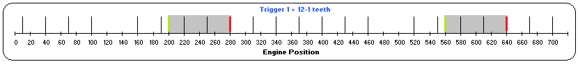
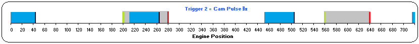
Looks for a Trigger 2 tooth within a specified window (length set by Window Length) before the Trigger 1 Sync Tooth (Trigger 1 Sync Tooth being X teeth after the Trigger 1 missing tooth gap with X being the value set in Trigger 1's Sync Tooth setting)
This sync mode will only work in 'Multi-Tooth / Missing' trigger mode. This mode is useful for engine with multiple teeth on the cam as you can specify a particular one for syncing (just make sure to account for any VVT cam swing).
In the example below Trigger 1's Sync Tooth setting would be set to 5 (tooth shown highlighted in red) and Window Length could be set to 30 degrees. If this was an intake cam with a 50deg cam swing (shown in blue) a Window Length of 80 degrees would cover the full swing while still syncing properly, the start point of an 80deg window has been indicated in green on the diagram with the end point being the Sync Tooth in red.
Trigger 1 - Multi-tooth / Missing |
|
Trigger 2 Sync Mode - Cam Pulse Window |
|
Supported engine configurations |
4 Stroke (with sequential or group fuel modes and distributed, wasted spark, or direct spark ignition modes) |
Notes |
With this trigger setup the ECU knows the engine position within a 720 degree engine cycle. The trigger 2 tooth being used for syncing cannot at any point be located in the Trigger 1 gap. |
·MAP Level
Ignores the Trigger 2 Type and instead uses the MAP runtime to detect the intake stroke.
This mode requires a MAP signal that is affected in one half of the engine cycle but not the other and so is suitable for 1 cylinder engines, 3 cylinder engines and engine with the MAP sensor attached to the runner of one cylinder (typically engines with ITBs). This sync mode will only work in 'Multi-Tooth / Missing' trigger mode. It is recommended that MAP is connected to An Volt 1 when using this mode so that it is included in the trigger scope.
The MAP Offset value is the threshold for how far the MAP value has to drop below the BAP value during an intake stroke while cranking to be recognised as the intake stroke half of the engine cycle. If the MAP value drops less than half of the MAP Offset value during that half engine cycle then it is considered to be the power stroke half of the engine cycle. If the MAP value dips to between half the MAP Offset value and the whole MAP Offset value below BAP during cranking it is considered an undefined half cycle and so the ECU will try to sync again on the next crank revolution.