Design of the toothed wheels used for crank and cam angle measurement is critical.It is not uncommon for installers to machine or modify wheels.
Design of the "Gap"
One or more missing teeth are often used to indicate a reference position. One of the most common problems encounter on after-market wheels and in fact on some OEM (eg BMW) wheels is incorrect design of the teeth and gap. Some important points regarding the issue shown below:
·This is only a problem when there are teeth missing.
·This is usually only a problem on high tooth count wheels (eg 60-2).
·This problem gets worse at higher RPM.
·This problem is usually only encountered using Reluctor Sensors. Hall Effect sensors usually do not suffer from this phenomenon.
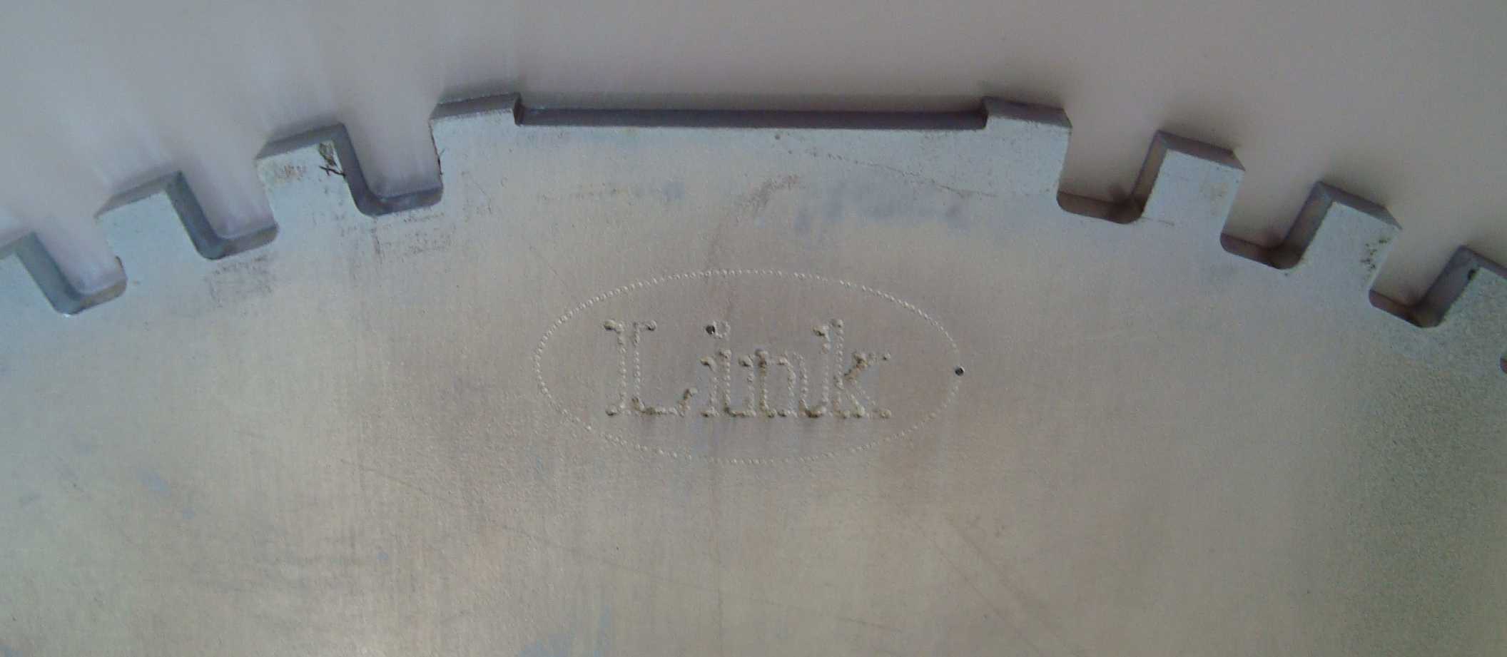
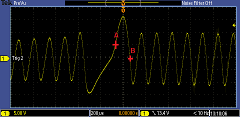
Incorrect design of the teeth around the gap can lead to a distortion of the sensors signal. There are a variety of contributing factors to this problem (electronic, magnetic), most of which can not be adjusted. The following pictures show a correctly designed wheel and the signal from that wheel at approx 7200 RPM.

Correctly designed gap
And the signal from the same wheel. Point A shows the arming voltage on the rising edge of the tooth after the gap. Point B shows the zero crossing. Point B is where the ECU sees the signal and uses it for engine position tracking. Note how the signal after point B goes well below zero volts.

Signal from correctly designed gap
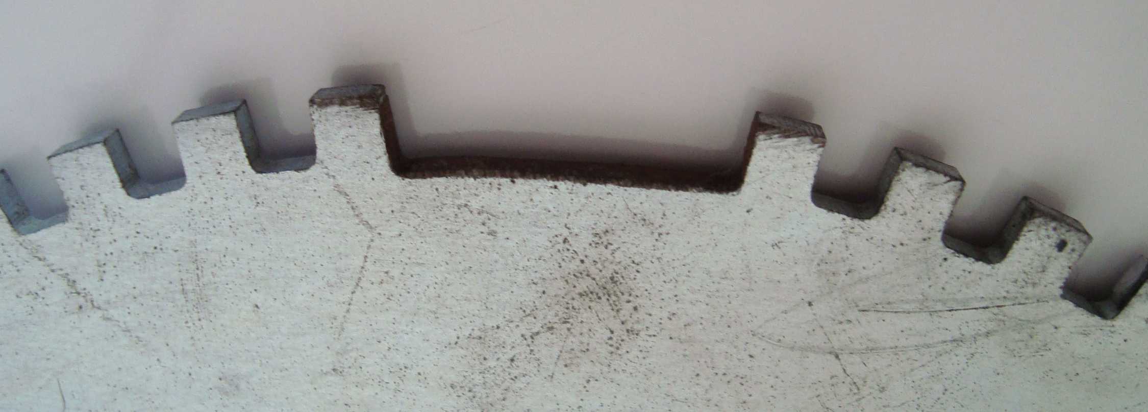
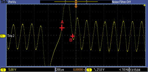
However, it is more common in after market wheels and even some OEM wheels to have an incorrectly designed gap. This causes a problem at very high RPM . The following pictures show an incorrectly designed wheel and the signal from that wheel at approx 7200 RPM.

Incorrectly designed gap
The signal from this incorrectly designed gap show a problem with the tooth after the gap. This signal was taken at approximately 7200 RPM.

Signal from incorrectly designed gap
Note the excessive amplitude of the signal as the sensor enters and exits the gap. But, more importantly notice what is happening at point B. As RPM increases the negative voltage of the tooth after the gap is reducing. In the picture the signal is just OK as it still passes through zero volts. However, at around 7500 RPM this signals negative amplitude at point B was above zero volts and the tooth was missed all together. This causes the next tooth to be the one seen after the gap resulting in a loss of tracking of engine position. In this case resulting in a six degrees advance in timing to all cylinders!


