When using a reluctor type trigger sensor it is necessary to correctly fill in a Trigger Arming Threshold Table.
The Trigger Arming Threshold table sets the voltage required to 'Arm' the trigger generation circuitry before waiting for a falling edge on the trigger signal. The purpose of the trigger arming circuitry is to improve the trigger inputs ability to reject interference and electrical noise, thus helping to eliminate false trigger signals. At low engine speeds (particularly when cranking), reluctor sensors produce a very low voltage signal. Therefore at low RPM a lower arming voltage is required. As engine speed increases so does the amplitude of the reluctor sensors signal. This allows higher arming thresholds to be used. Different arming voltages can be entered for each 1000 RPM.
Correctly setting up the Trigger Arming Threshold Table
To correctly setup the Trigger Arming Threshold Table it is necessary to be able to read the half wave amplitude (the height of the waveform above the zero point) of the trigger signal, there are two methods for doing this:
·Oscilloscope - Use an oscilloscope to measure the trigger signal amplitude. This is the preferred method.
·Trigger Scope - Most Link G4X ECUs have a feature called Trigger Scope which measures the voltage on the ECUs triggers and presents the data in a visual form similar to an oscilloscope.
An oscilloscope will be used in this explanation of setting up the Trigger Arming Threshold table, however using Trigger Scope is a very similar process. Before commencing make sure that the engine speed is reading correctly, that the ECU is connected to PCLink, and that the engine speed is visible.
The Trigger Arming Threshold Table has an axis that increments in steps of 1000 RPM. For each step of 1000 RPM the following process needs to be followed:
1.Increase the engine speed until it matches the RPM of the trigger arming voltage table cell to be set.
2.Adjust the voltage/division and time/division setting until the teeth of the trigger wheel are clearly visible.
3.Press the 'Pause' button on the oscilloscope. Allow the engine to return to idle.

Measuring the trigger signal amplitude at 1000 RPM
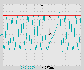
4.Go to the Trigger Arming Threshold Table (for the relevant trigger), select the correct cell (same RPM as oscilloscope capture) and enter a value that is half the voltage of the tooth with the lowest amplitude. For the oscilloscope image above this would be 2.5 volts, as the change in voltage between the two red lines is 5.0 volts and the value entered needs to be half of this.
5.Repeat steps one to four until the remaining cells in the Trigger Arming Threshold Table have been correctly filled in.
When determining the correct value for the zero RPM cell in the Trigger Arming Threshold Table you can disable the engines fuel and ignition systems and then perform the steps above at the engines cranking speed. Enter the value obtained in the zero RPM cell.


