The Knock Audio function is a feature to help identify knock sensor frequency. It is able to analyze the audio output of the Knock Amplifier and help determine the correct frequency filter for your knock sensor. The Knock Audio function does this by using the audio output from the Knock Amplifier and inputting it into your PCs sound card. The audio signal is then visually represented on the screen to help identify the frequency at which knock is being measured.
Setting up Knock Audio
1.Connect the Knock Amplifiers (or KnockBlock) audio output to the PCs microphone input using a double ended 3.5mm audio cable.
2.Open the Knock Audio window (PCLink > Tuning > Knock Audio).
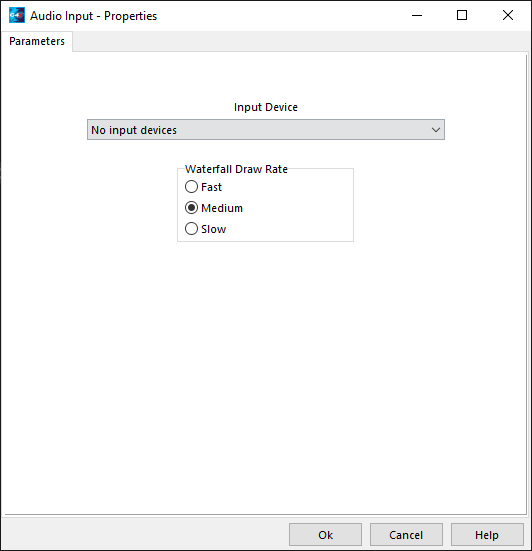
3.Select the Audio Input Device you have the Knock Amplifier connected to.
4.Select the Waterfall draw rate. This controls the rate at which the Knock Audio visual display is re-drawn at, set this to fast. If you encounter problems with your PC being too slow drop the rate back to medium or slow. Press OK.
Using Knock Audio
WARNING
Knock can potentially damage an engine, extreme care must be taken. Link will take no responsibility for any damage caused to an engine when configuring Knock Audio or Knock Control. It is the tuners responsibility to take all measures to protect the engine and users.
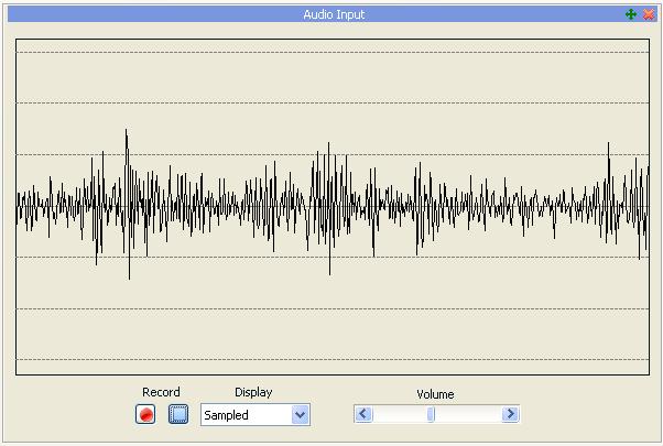
1.Make sure the display mode is set to Sampled. Start your engine up, and make sure the ignition timing is conservative. Click the record button in the Knock Audio window and increase engine RPM to above idle (1500 to 200 RPM on most applications). Adjust the volume slider to the point where the peaks of the signal are reaching the area between the first and second line from the center.
2.Change the display mode to Waterfall. Click the stop button to stop the image recording. Look at the display and compare it to the two images below to help determine if the knock sensor type is a narrow-band or wide-band sensor. Adjusting the contrast can make the image easier to interpret.
Narrow-band Knock sensor
|
|
|
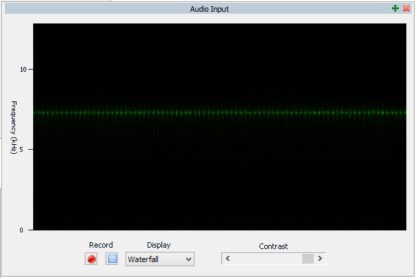
A narrow-band knock sensor will display as a thin band of colour occurring at a particular frequency. A lot of factory knock sensors are narrow band sensors as they are selected to match the knock frequency of the engine.
If the Knock Audio waterfall display has a single band of colour, look at the y axis of the waterfall display to determine the frequency it occurs at. In this example image the frequency is at approximately 7 kHz.
The frequency filter on the Knock Amplifier or Link ECU can now be setup to match the frequency determined.
Note: Some narrow-band knock sensors, known as second harmonic knock sensors, operate at a frequency above 10 kHz. To expand the viewable frequency range in the waterfall display drag the top or bottom edge of the Knock Audio window. |
Wide-band Knock sensor
|
|
|
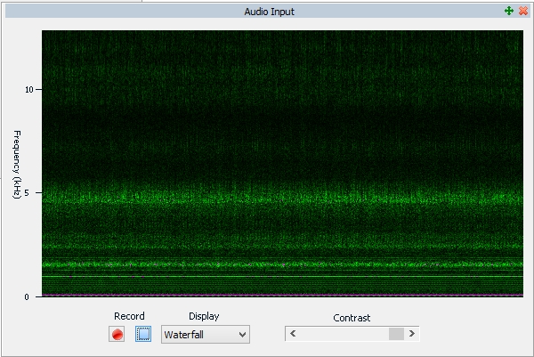
A wide-band knock sensor will cause the Knock Audio waterfall display to show an image that contains colour (noise) at a wide range of frequencies. This makes it difficult to determine the correct frequency filter to select when setting up a Knock Amplifier or Link ECU.
There are two solutions to this problem. The first solution is best as it does not risk engine damage. Use of the second method is at the tuners risk.
·Use the calculation method for determining the knock frequency of the engine:
Knock Resonant Frequency (Khz) = 1800/(3.14 * piston diameter in mm)
or
·Take a screen capture of the waterfall display with the engine running conservative ignition timing. Then record another waterfall display image with the timing very momentarily advanced enough to cause light engine knock. Compare the two waterfall display images, the second image should have colour (noise) in a frequency range the first image does not. Where this colour occurs is the frequency range the engine knock is occurring at.
The frequency filter on the Amplifier or Link ECU can now be setup to match the frequency determined.
|
Detecting Engine Knock
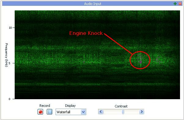
If engine knock occurs this will be visible in the waterfall display as the colour pink, the intensity of the knock will correspond to the amount of pink that shows in the image. In order for the engine knock to show correctly the contrast slider must be adjusted so that normal engine noise does not show up as pink. The image below is an example of engine knock being present in the waterfall view.
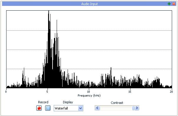
Right clicking on an area in the waterfall view and selecting 'Show FFT for point' will cause that 'vertical slice' of the waterfall view to be displayed as a Fast Fourier Transform image. This is useful to help analyse the noise that Knock Audio is receiving. The FFT image below is from the point where pink is showing in the image up. As you can see there in the FFT image, there is a sharp spike in noise intensity in the 5 to 7 kHz range.
Holding the shift key while pressing the left or right arrow key will cause the FFT view to move one 'vertical slice' of the waterfall view to the left or right. This is useful when trying to identify a very brief period of engine knock.
Knock Audio Fault Finding
·If you can not obtain a suitable level of signal in the Sampled view by using the Knock Audio volume slider you may need to adjust the Knock Amplifier or PCs main volume control.
·If you can not obtain a signal in the Knock Audio confirm that the signal is reaching the PC correctly by listening for the engine noise through your PC speakers. On some versions of windows this involves changing your microphone properties in control panel.
·If you have a large spike in the FFT view that is always present (even without the engine knocking) it is possible that you are picking up external noise. Check the Knock system wiring, confirming that the shielding, GND and signal are connected correctly. See Knock Inputs for more detail on knock sensor wiring.
·Some older PCs and laptops have inferior sound-cards that are unable to produce the volume or sound quality required for Knock Audio. If you are unable to resolve problems with noise try another PC or laptop.


