Some sensor types do not have predefined calibrations or have calibrations that aren't in the Link software. When a sensor without a built in calibration is used a calibration table or linear calibration can be setup to provide the correct calibration to the input signal.
Note: Temperature, Pressure and Lambda sensor calibration numbers can be found HERE. Check these against your sensor first before creating a custom cal.
Linear Calibrations are used for sensors with a linear relationship between the input and output value such as most MAP sensors.
Calibration Tables are used for sensors with a non linear relationship between the input value and output value such as temperature sensors.
Linear Calibration
Three linear calibrations are available, to use a particular linear calibration for an input it will first need to be setup. Each linear calibration has six settings and these are described below. The calibration can be selected in the calibration list of the input.
·Label - Used to add a short description to your calibration.
·Output Units - Used to select the output units of your calibration, this determines the number of decimal points and range of values your output settings can have as well as allowing the entered output values to change as the unit being used is changed. For example if the the Output units is set to pressure and the current pressure units being used are psi then Output Value A and B can be entered in psi and if the units being used are changed to kPa then the values shown in Output Value A and B are changed to match. Pressing U changes units as described here.
·Input Value A - This is the sensor VOLTAGE at the first calibration point.
·Output Value A - This is the sensor MEASUREMENT at the first calibration point.
·Input Value B - This is the sensor VOLTAGE at the second calibration point.
·Output Value B - This is the sensor MEASUREMENT at the second calibration point.
Example
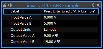
The air fuel ratio corresponding to 0V is 9.0:1 while the air fuel ratio corresponding to 5V is 19.0:1. This information should be entered in the following way.
·Output Units - Set to Lambda and change the Lambda units to AFR (description of how to change units here).
·Input Value A - 0.00 V This is the sensor voltage at the first point.
·Output Value A - 9.00 AFR This is the AFR at 0.00 V
·Input Value B - 5.00 V This is the sensor voltage at the second point.
·Output Value B - 19.00 AFR This is the AFR at 5.00 V
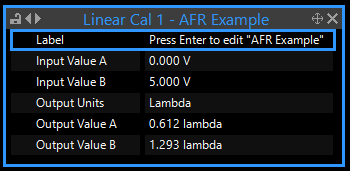
The units can be changed back to Lambda after the two output values have been set, the output values will change to show the Lambda values (0.612 for A and 1.293 for B with a stoichiometric value of 14.7AFR) when this is done.
An image of the setup with Imperial units and another image of Metric units is shown below, 'U' was used to switch between the two.

Linear Cal with Imperial units

Linear Cal with Metric units
Note: Linear calibrations will extrapolate values outside of the voltage set points.
Calibration Tables
Ten calibration tables are available, to use a particular calibration for an input it will first need to be setup. Each calibration table has three settings and a table to fill out, these are described below. The calibration can be selected in the calibration list of the input.
·Label - Used to add a short description to your calibration.
·Input Units - Used to select whether the calibration is specified in terms of resistance (Ohms) or voltage, resistance is useful for temperature inputs as the ECU can adjust the calibration based on the pull-up.
·Output Units - Used to select the output units of your calibration, this determines the number of decimal points and range of values your output settings can have as well as allowing the entered output values to change as the unit being used is changed. For example the table can be filled out with values in psi and the units can be automatically converted to kPa. Pressing U changes units as described here.
·Calibration Table - This is where the sensor calibration information is entered.
The calibration table has the input units on the X axis and the output values are entered into the table, the axis can be adjusted to suit in the same manner as other tables.
Example
Non-linear temperature sensor data is entered into Cal Table 1. The information should be entered in the following way.
·Input Units - Set to Ohms as this is what the temperature sensor outputs
·Output Units - Set to °C as this is the unit type we want the temperature in.

Cal Table with Metric units
The values in the table will change when the PCLink units are changed, for example if the above table was made with the units set to degrees C the table will look like the below image when 'U' is pressed to change to imperial units.

Cal Table after changing units to Imperial
Note: Calibration Tables will not extrapolate values off either end of the table, they will be capped at the values at either end of the table. A linear interpolation will be applied between the table cells however.


