


The following are some examples of setting up Link G4X ECU to communicate with an OEM CAN bus. Most of the information for OEM CAN bus devices is not publicly available and often has to be reversed engineered using a CAN bus sniffer or analyser.
·Wheel Speed from ABS Control to ECU (Receive)
·RPM from ECU to Factory dash (Transmit)
·AC (Air Conditioning) button press from Body Control Module to ECU (Receive)
Example: Wheel Speed from ABS Control to ECU
Known information:
·CAN bus speed of 500 kbit/s
·ABS Control transmits:
·Wheel Speeds on ID 1184
·Byte order of MS First
·Each Wheel Speed has a width of 16 bits (2 bytes)
·Type is Unsigned
·CAN ID format is Standard
·The number the ABS Control transmits on the CAN bus is in units of 0.01 km/h (ie increments by 1 for each 0.01 km/h increase in Wheel Speed).
·An eight byte CAN frame with the following format:

·To configure the ECU to receive from the ABS controller:
1. Connect CAN H and CAN L pins on ECU to the vehicles CAN bus.
2. Open the CAN setup window in PCLink. (ECU Controls > CAN Setup)
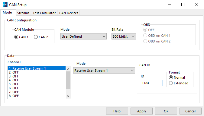
3. Select the CAN module connected to the vehicles CAN bus.
4. Set the Mode to User Defined and the Bit Rate to 500 kbit/s.
5. Select a spare CAN channel from the list (we are using 'one' in our example), set the Mode to "Receive User Stream X", where X is the next un-used Receive/Transmit number (we are using 'one' in our example).
6. Set the ID field to match the ID the ABS Control is transmitting the Wheel Speed on (ID 1184).
7. Set the Format to Standard.
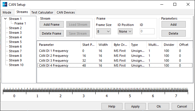
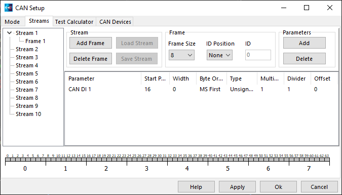
8. Change to the Streams tab of the CAN Setup window, select stream one and click 'Add Frame'.
9. Select frame one in the list view on the left. Click 'Add' from the parameters section, navigate to the CAN Digital Input section and select CAN DI 1 Frequency. Click OK and confirm CAN DI 1 Frequency is now listed.
10. Add the CAN DI 2 Frequency, CAN DI 3 Frequency and CAN DI 4 Frequency parameters like you did for CAN DI 1 Frequency. Confirm that all four CAN DI 1 Frequencies are now listed.
11. Determine the Multiplier, Divider and Offset required for each parameter.
Wheel Speed from ABS Controller (km/h) |
CAN number sent by ABS Controller |
Multiplier/Divider |
ECU/PCLink Number (km/h) |
0.00 |
0 |
1/100 |
0.0 |
0.01 |
1 |
1/100 |
0.0 |
1.00 |
100 |
1/100 |
1.0 |
26.00 |
2600 |
1/100 |
26.0 |
12. Select CAN DI 1 Frequency and confirm the Start Pos is 0, the Width is 16, the Byte Order is MS, the Type is Unsigned, the Multiplier is 1, the Divider is 100, and the Offset is 0.
13. Set the CAN DI 2 Frequency, CAN DI 3 Frequency and CAN DI 4 Frequency parameters up also. CAN DI 2 Frequency Start Pos = 16, CAN DI 3 Frequency Start Pos = 32, CAN DI 4 Frequency Start Pos = 48. All other settings are the same as in CAN DI 1 Frequency.
14. Click Apply and then OK. Remember to perform a Store (F4).
15. Navigate to Chassis and Body -> Speed Sources -> LF Wheel Speed and set the source to CAN DI 1 Frequency. Leave Calibration as 0 unless you want to correct for non factory wheel sizes.
16. Repeat for RF, LR and RR Wheel Speeds using CAN DI 2, 3, and 4 Frequencies.
17. Look at the Wheel Speeds on the Misc tab of the runtime values window (F12). Have someone drive the vehicle while watching the wheel speeds, confirm that the speeds displayed are correct.
Example: RPM from ECU to Factory Dash
Known information:
·CAN bus speed of 1 Mbit/s
·Dash expects:
·RPM on ID 640
·Byte order of MS First
·RPM has a width of 16 bits (2 bytes)
·Type is Unsigned
·CAN ID format is Standard
·The number on the CAN bus to increment by 1 for each increase of 4 RPM.
·A Transmit rate of 100 Hz

1. Connect CAN H and CAN L pins on ECU to the vehicles CAN bus.
2. Open the CAN setup window in PCLink. (ECU Controls > CAN Setup)
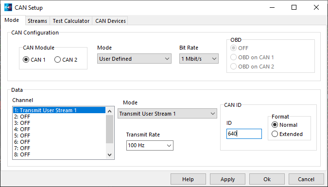
3. Select the CAN module connected to the vehicles CAN bus.
4. Set the Mode to User Defined and the Bit Rate to 1 Mbit/s.
5. Select a spare CAN channel from the list (we are using 'one' in our example), set the Mode to "Transmit User Stream X", where X is the next un-used Receive/Transmit number (we are using '1' in our example).
6. Set the ID field to match the ID the Dash is expecting the RPM on (ID 640).
7. Set the Format to Standard.
8. Set the Transmit Rate to 100Hz.
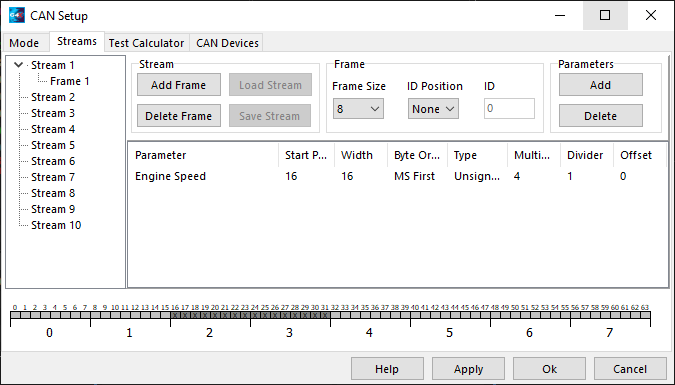
8. Change to the Streams tab of the CAN Setup window, select stream one and click 'Add Frame'.
9. Select frame one in the list view on the left. Click 'Add' from the parameters section, navigate to the Triggers section and select Engine Speed. Click OK and confirm Engine Speed is now listed.
10. Determine the Multiplier, Divider and Offset required.
ECU/ PCLink Number |
Multiplier/ Divider |
CAN Number |
Dash RPM |
0 |
1/1 |
0 |
0 |
1 |
1/1 |
1 |
0.25 |
1 |
4/1 |
4 |
1 |
100 |
4/1 |
400 |
100 |
4200 |
4/1 |
16800 |
4200 |
In row one of the table above the ECU Number is 0 and the Dash RPM is zero, no problems here, the ECU value is the same as the Dash RPM. However in row two we have increased the ECU Number and we can see that the ECU Number is not the same as the Dash RPM, it is 4x higher! If we increase the Multiplier to 4 (row three) we can see that the Dash RPM is the same as the Engine Number, good. In rows four and five we again check that the Dash RPM is the same as the ECU Number, and it is still correct. Therefore the required Multiplier is 4, the required Divider is 1 and the required Offset is 0.
11. Select Engine Speed and confirm the Start Pos is 16, the Width is 16, the Byte Order is MS, the Type is Unsigned, the Multiplier is 4, the Divider is 1, and the Offset is 0.
12. Click Apply and then OK. Remember to perform a Store (F4).
15. Look at the Dash RPM while someone drives the vehicle, confirm that the Engine RPM displays correctly.
Example: Air Conditioning (AC) button press from Body Control Module (BCM) to ECU
Known information:
·CAN bus speed of 500 kbit/s
·BCM transmits:
·AC Button Status press on ID 1329
·Byte order of MS First
·The AC Button Status has a width of 1 bit (less than 1 byte)
·Type is Unsigned
·CAN ID format is Standard
·The number the BCM transmits on the CAN bus for AC Button Status is either 0 (Inactive) or 1 (Active).

1. Connect CAN H and CAN L pins on ECU to the vehicles CAN bus.
2. Navigate to Chassis and Body>AC Clutch Control and set AC Request Source to CAN DI 1.
3. Open the CAN setup window in PCLink. (ECU Controls > CAN Setup)
4. Select the CAN module connected to the vehicles CAN bus.
5. Set the Mode to User Defined and the Bit Rate to 500 kbit/s.
6. Select a spare CAN channel from the list (we are using 'one' in our example), set the Mode to "Receive User Stream X", where X is the next un-used Receive/Transmit number (we are using 'one' in our example).
7. Set the ID field to match the ID the BCM is transmitting the AC Button Status on (ID 1329).
8 Set the Format to Standard.

9. Change to the Streams tab of the CAN Setup window, select stream one and click 'Add Frame'.
10. Select frame one in the list view on the left. Click 'Add' from the parameters section, navigate to the CAN>CAN Digital Input section and select CAN DI 1 (Status). Click OK and confirm CAN DI 1 is now listed.
11. Determine the Multiplier, Divider and Offset required. When setting CAN up for a Status a Multiplier of 1 and a Divider of 1 are always used, the table below helps understand this.
AC Button Status |
CAN number |
Multiplier/Divider |
CAN DI Number |
0 (Inactive) |
0 |
1/1 |
0 (Inactive) |
1 (Active) |
1 |
1/1 |
1 (Active) |
In row one of the table above the AC Button Status is 0 (Inactive) and the CAN DI value is 0 (Inactive), no problems here, the CAN DI is the same as the AC Button Status. In row two we can see the AC Button Status is now 1 (Active) and the CAN DI value is also 1 (Active). We now know that both states for the AC Button match what the CAN DI expects.
12. Confirm the CAN DI 1 Start Pos is 16, the Width is 1, the Byte Order is MS, the Type is Unsigned, the Multiplier is 1, the Divider is 1, and the Offset is 0.
13. Click Apply and then OK. Remember to perform a Store (F4).
14. Navigate to Chassis and Body -> AC Clutch Control and set AC Request Source to CAN DI 1.
15. Look at the AC Request Status on the General tab of the runtime values window (F12). Confirm that the AC Request Status reads correctly for the AC Button position.