


The following CAN devices have pre-configured modes. Expand the sections below to read the setup notes for each device.
·ECUMaster CAN Switch Board V3
Setting up the Link ECU:
1.Open the CAN Setup window (PCLink > ECU Controls > CAN Setup).
2.On a spare User CAN Stream, click Load Stream and select the file "AEM EGT 30-2224 Stream 1 Extended ID 47616".
3.On a second spare User CAN Stream, click Load Stream and select the file "AEM EGT 30-2224 Stream 2 Extended ID 47617".
4.Select the CAN module to be used.
5.Set the Mode to 'User Defined'.
6.Configure the Bit Rate to 500 kbit/s
7.Select a spare CAN channel.
8.Select Receive User Stream x from the Mode drop-down menu. Where x is the number of the User CAN Stream the "AEM EGT 30-2224 Stream 1 Extended ID 47616" file was previously loaded into.
9.Set the CAN ID to extended format and 47616.
10.Select the second Receive User Stream x from the Mode drop-down menu. Where x is the number of the User CAN Stream the "AEM EGT 30-2224 Stream 2 Extended ID 47616" file was previously loaded into.
11.Set the CAN ID of the second receive stream to extended format and 47617.
12.Click Apply and then OK.
13.Make sure a Store (F4) is performed.
The AEM EGT 30-2224 data will come through to the Link G4X ECU as CAN TC Cyl 1 to 8. You can use anywhere from 1 to 8 EGT thermocouples.
Setting up the AEM X-Series UEGO Gauge
1.Refer to manufacturers instructions for selecting the correct CAN Id using the gauges setup menu.
Setting up the Link ECU:
1.Open the CAN Setup window (PCLink > ECU Controls > CAN Setup).
2.On a spare User CAN Stream, click Load Stream and select the file "AEM X-Series UEGO Gauge.lcs".
3.Select the CAN module to be used.
4.Set the Mode to 'User Defined'.
5.Configure the Bit Rate to 500 kbit/s
6.Select a spare CAN channel.
7.Select Receive User Stream x from the Mode drop-down menu. Where x is the number of a User CAN Stream the file was previously loaded into.
8.Set the CAN ID to extended format.
9.Set the CAN ID to suit the ID selected in the gauge. If the gauge is set to ID 1, enter CAN ID 384, for gauge ID 2 enter 385, ID3 = 386, etc..
10.Click Apply and then OK.
11.Make sure a Store (F4) is performed.
Using the supplied stream file, the Lambda value will come through on the Lambda 1 parameter. If this is not desirable, the user stream can be altered to use the Lambda 2 parameter. Make sure Lambda 1 (or Lambda 2 if stream has been altered to use that) has been set to Link CAN.
AiM MXS Strada, AiM MXG Strada and AiM MXL Pista
Setting up the Link ECU:
1.Open the CAN Setup window (PCLink > ECU Controls > CAN Setup).
2.Select the CAN module to be used.
3.Set the Mode to 'User Defined'.
4.Configure the Bit Rate to 1 Mbit/s
5.Select a spare CAN channel.
6.Select 'Transmit Link AIM MXS Strada Dash' from the Mode drop-down menu.
7.Set the CAN ID to 1000 (Normal format).
8.Set the transmit rate to 20Hz
9.Make sure no other CAN channels are configured on the same CAN ID.
10.Click Apply and then OK.
11.Make sure a Store (F4) is performed.
Note: It's recommended to make sure you have the latest dash firmware (and ECU Firmware).
AiM MXL Pista Dash Setup (Not applicable to MXS Strada or MXG Strada)
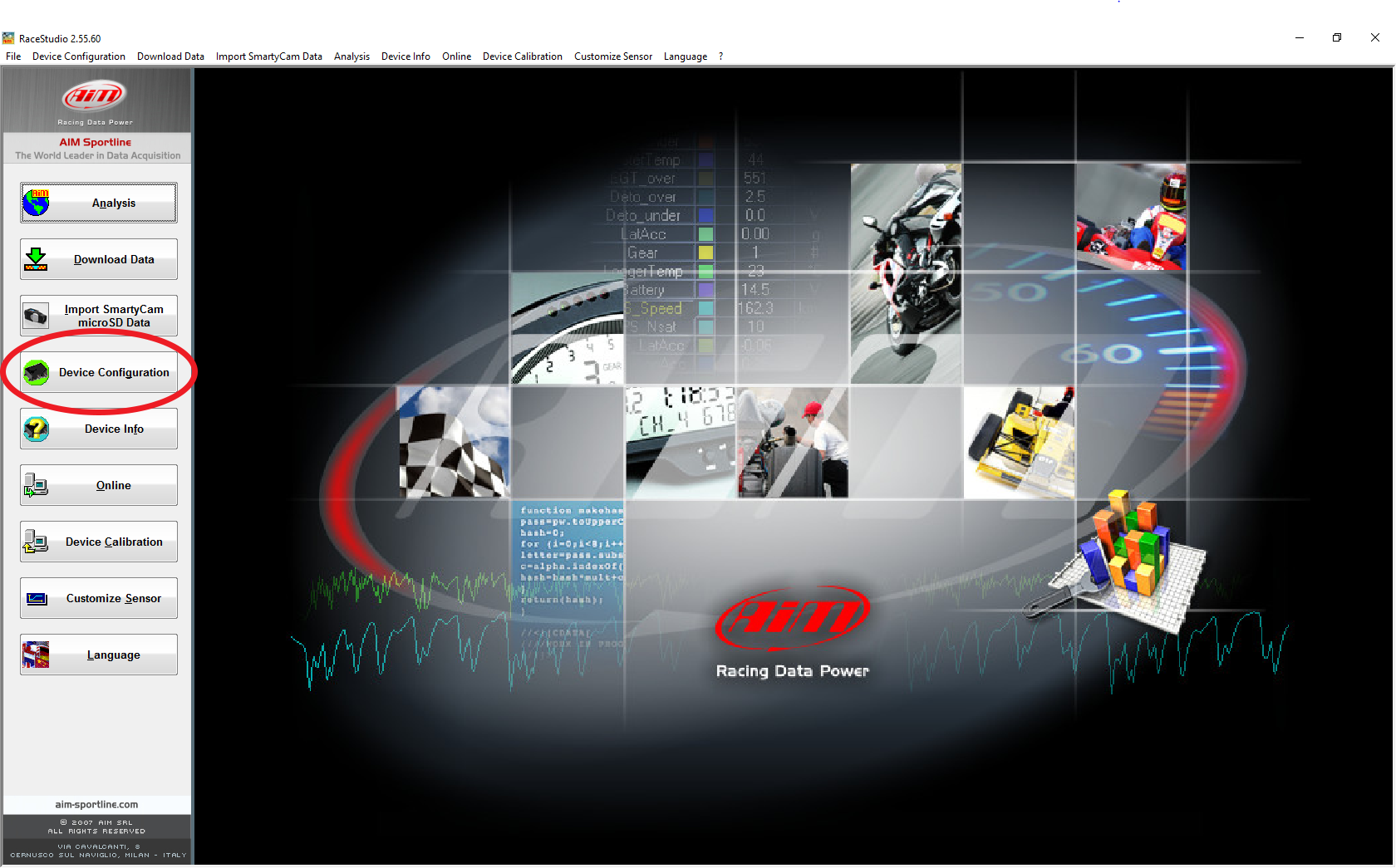
1. Start Aim Race Studio 2, select Device Configuration and then your dash type (MXL Pista in this case).
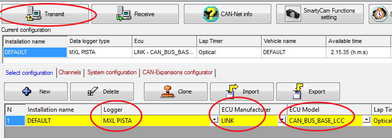
2. Make sure the Logger is set to MXL Pista and ECU Manufacturer is set to Link. For ECU Model select: CAN_BUS_BASE_LCC
3. Click Transmit to store the settings to the Aim dash.
4. Cycle the power supply to the ECU and dash. The two devices should now be communicating over CAN.
Channels displayed on the dash must be configured in Race Studio 2.
Setting up the Link ECU:
1.Open the CAN Setup window (PCLink > ECU Controls > CAN Setup).
2.Select the CAN module to be used.
3.Set the Mode to 'User Defined'.
4.Configure the Bit Rate to 1 Mbit/s
5.Select a spare CAN channel.
6.Select 'Transmit Generic Dash' from the Mode drop-down menu.
7.Set the CAN ID to 1000.
8.Make sure no other CAN channels are configured on the same CAN ID.
9.Click Apply and then OK.
10.Make sure a Store (F4) is performed.
Setting up the DisplayLink:
1.In the DisplayLink setup menu, select Display Settings. Select ECU Type. Choose Link G4 UCAN.
2.Make sure the CAN ID matches the one setup in the ECU (1000).
3.The green light on the DisplayLink will come on solid when communication is working correctly.
The DisplayLink uses the same data format as Generic Dash
Setting up the Link ECU:
1.Open the CAN Setup window (PCLink > ECU Controls > CAN Setup).
2.Select the CAN module to be used.
3.Set the Mode to 'User Defined'.
4.Configure the Bit Rate to 500 kbit/s
5.Select a spare CAN channel.
6.Select 'Receive DIYAutoTune CAN-EGT' from the Mode drop-down menu.
7.Set the CAN ID to anything between 1 and 2047. The actual number used is not important as the IDs for this CAN mode are hard coded.
8.Make sure no other CAN channels are configured on the same CAN ID as the DIYAutoTune CAN-EGT channel.
9.Click Apply and then OK.
10.Make sure a Store (F4) is performed.
Setting up the DIYAutoTune CAN-EGT:
1.Refer to manufacturers instructions.
2.Use 'TunerStudio' to confirm the 'Main Controller CAN ID' is set to 1. This is the default setting.
The DIYAutoTune CAN-EGT data will come through to the Link G4X ECU as CAN TC Cyl 1 to 8. You can use anywhere from 1 to 8 EGT thermocouples.
Ecotrons ALM (Advanced Lambda Meter)
Setting up the Link ECU:
1.Open the CAN Setup window (PCLink > ECU Controls > CAN Setup).
2.Select the CAN module to be used.
3.Set the Mode to 'User Defined'.
4.Configure the Bit Rate to 250 kbit/s
5.Select a spare CAN channel.
6.Select 'Receive User Stream X' from the Mode drop-down menu (Where X is the next unused transmit or receive user stream number).
7.Set the CAN ID to 218038273.
8.Set the Format to Extended.
9.Change to the Streams tab of the CAN Setup window. Select Stream X and then click Load Stream.
10.Select 'Ecotrons ALM.lcs' and click the Open button. If you can not see the correct file, you can find it in the CAN folder of your PCLink install.
11.Make sure no other CAN channels are configured on the same CAN ID as the Ecotrons ALM CAN channel.
12.Click Apply and then OK.
13.Make sure a Store (F4) is performed.
Setting up the Ecotrons ALM:
1.Refer to manufacturers instructions.
The Ecotrons ALM data will come through to the Link G4X ECU as Lambda 1, make sure Lambda 1 has been set to Link CAN.
Ecotrons Dual ALM (Advanced Dual Lambda Meter)
Setting up the Link ECU:
1.Open the CAN Setup window (PCLink > ECU Controls > CAN Setup).
2.Select the CAN module to be used.
3.Set the Mode to 'User Defined'.
4.Configure the Bit Rate to 250 kbit/s
5.Select a spare CAN channel.
6.Select 'Receive User Stream X' from the Mode drop-down menu (Where X is the next unused transmit or receive user stream number).
7.Set the CAN ID to 218038273.
8.Set the Format to Extended.
9.Change to the Streams tab of the CAN Setup window. Select Stream X and then click Load Stream.
10.Select 'Ecotrons ALM.lcs' and click the Open button. If you can not see the correct file, you can find it in the CAN folder of your PCLink install.
11.Change back to the Mode tab, select the next spare CAN channel.
12.Select 'Receive User Stream Y' from the Mode drop-down menu (Where Y is the next unused transmit or receive user stream number)
13.Set the CAN ID to 218038274.
14.Set the Format to Extended.
15.Change to the Streams tab of the CAN Setup window. Select Stream Y and then click Load Stream.
16.Select 'Ecotrons ALM Dual.lcs' and click the Open button. If you can not see the correct file, you can find it in the CAN folder of your PCLink install.
17.Make sure no other CAN channels are configured on the same CAN ID as the Ecotrons ALM Dual CAN channels.
18.Click Apply and then OK.
19.Make sure a Store (F4) is performed.
Setting up the Ecotrons Dual ALM:
1.Refer to manufacturers instructions.
The Ecotrons Dual ALM data will come through to the Link G4X ECU as Lambda 1 and Lambda 2, make sure Lambda 1 & 2 have been set to Link CAN
Note this device uses two CAN IDs to send 2 separate CAN messages, the first message contains channels 1-4 and the second message contains channels 5-8. So if you are using this device on a 4 cylinder then you only need to set up the first stream (ID1552)
Setting up the Link ECU:
1.Open the CAN Setup window (PCLink > ECU Controls > CAN Setup).
2.Select the CAN module to be used.
3.Set the Mode to 'User Defined'.
4.Configure the Bit Rate to 1 Mbit/s
5.Select a spare CAN channel.
6.Select 'Receive User Stream X' from the Mode drop-down menu (Where X is the next unused transmit or receive user stream number).
7.Set the CAN ID to 1552.
8.Set the Format to Normal.
9.Change to the Streams tab of the CAN Setup window. Select Stream X and then click Load Stream.
10.Select 'Ecumaster Egt2CAN Stream1 ID1552.lcs' and click the Open button (find this in CAN folder of your PCLink install).
11.If only 4 channels are needed then jump to step 18 now. If more than 4 channels are needed continue from step 12.
12.Change back to the Mode tab, select the next spare CAN channel.
13.Select 'Receive User Stream Y' from the Mode drop-down menu (Where Y is the next unused transmit or receive user stream number)
14.Set the CAN ID to 1553.
15.Set the Format to Normal.
16.Change to the Streams tab of the CAN Setup window. Select Stream Y and then click Load Stream.
17.Select Ecumaster Egt2CAN Stream2 ID1553.lcs' and click the Open button.
18.Click Apply and then OK.
19.Make sure a Store (F4) is performed.
This device is highly configurable, settings like Bit Rate and CAN IDs will depend on how the device has been setup. It is also possible to edit the setup in the Link ECU to change which pin on the board affects which runtime value/status in the ecu and vice versa.
Setting up the Link ECU:
1.Open the CAN Setup window (PCLink > ECU Controls > CAN Setup).
2.Select the CAN module to be used.
3.Set the Mode to 'User Defined'.
4.Configure the Bit Rate to the same Bit Rate that the Switch Board is using.
5.Select a spare CAN channel.
6.Select 'Receive User Stream X' from the Mode drop-down menu (Where X is the next unused transmit or receive user stream number).
7.Set the CAN ID to 1600 (0x640 in hex) and the Format to Normal (This is the default base id and so will differ if the BASE ID value has been changed in the device).
8.Change to the Streams tab of the CAN Setup window. Select Stream X and then click Load Stream.
9.Select 'ECUMaster Switchboard V3 Receive Stream 1 Use ID 1600.lcs' and click the Open button (find this in CAN folder of your PCLink install).
10.Change back to the Mode tab, select the next spare CAN channel.
11.Repeat steps 6-10 for the other two ECUMaster Switchboard lcs files, note that the file name indicates whether the file needs to be setup to transmit or receive and the IDs are always relative to the base Id.
12.Click Apply and then OK.
13.Make sure a Store (F4) is performed.
The 'Transmit Generic Dash' mode sends out a range of common parameters, it is useful for dashes that are able to have a custom configuration. The parameters that are sent are in the table below.
Setting up the Link ECU:
1.Open the CAN Setup window (PCLink > ECU Controls > CAN Setup).
2.Select the CAN module to be used.
3.Set the Mode to 'User Defined'.
4.Configure the Bit Rate to match what the dash requires.
5.Select a spare CAN channel.
6.Select 'Transmit Generic Dash' from the Mode drop-down menu.
7.Set the CAN ID to match what the dash expects.
8.Set the Transmit Rate to 20Hz or what the dash expects.
9.Make sure no other CAN channels are configured on the same CAN ID as the Generic Dash channel.
10.Click Apply and then OK.
11.Make sure a Store (F4) is performed.
Setting up the Generic Dash:
1.The dash will need to be configured to match the data layout in the tables below.
All parameters are sent as 16 bit unsigned numbers, with low byte first. Some parameters must be multiplied or offset (constant value added) to get the correct calibrated value. The limits flags are sent through as a bit field (described below).
Data 0 |
Data 1 |
Data 2-3 |
Data 4-5 |
Data 6-7 |
|
Frame 1 |
0 |
0 |
Engine Speed Display (RPM) = Raw Range = 0 - 15000 RPM |
MAP Display (kPa) = Raw Range = 0 - 650 kPa |
MGP Display (kPa) = Raw -100 Range = -100 - 550 kPa |
Frame 2 |
1 |
0 |
Barometric Pressure Display (kPa) = Raw * 0.1 Range = 0 - 200 kPa |
TPS Display (%) = Raw * 0.1 Range = 0-100% |
Injector DC Display(%) = Raw * 0.1 Range = 0-100 % |
Frame 3 |
2 |
0 |
Injector DC (Sec) Display (%) = Raw * 0.1 Range = 0 - 100% |
Injector Pulse Width (Actual) Display (ms) = Raw * 0.001 Range = 0 - 65 ms |
ECT Display (deg C) = Raw - 50 Range = -50 - 205 deg C |
Frame 4 |
3 |
0 |
IAT Display (deg C) = Raw - 50 Range = -20 - 205 deg C |
ECU Volts Display (V) = Raw * 0.01 Range = 0 - 65 V |
MAF Display (g/s) = Raw * 0.1 Range = 0 - 6500 g/s |
Frame 5 |
4 |
0 |
Gear Position Display (gear) = Raw Range = 0 - 8,P,R,N,D,H,L,- |
Injector Timing Display (deg) = Raw Range = 0 - 719 deg |
Ignition Timing Display (deg) = (Raw * 0.1) - 100 Range = -100 - 100 deg |
Frame 6 |
5 |
0 |
Cam Inlet Bank 1 Display (deg) = Raw * 0.1 Range = 0 - 60 deg |
Cam Inlet Bank 2 Display (deg) = Raw * 0.1 Range = 0 - 60 deg |
Cam Exhaust Bank 1 Display (deg) = Raw * -0.1 Range = -60 - 0 deg |
Frame 7 |
6 |
0 |
Cam Exhaust Bank 2 Display (deg) = Raw * -0.1 Range = -60 - 0 deg |
Lambda 1 Display (Lambda) = Raw * 0.001 Range = 0 - 3.000 Lambda |
Lambda 2 Display (Lambda) = Raw * 0.001 Range = 0 - 3.000 Lambda |
Frame 8 |
7 |
0 |
Trig 1 Error Counter Display (counts) = Raw Range = 0 - 255 |
Fault Codes Display (code) = Raw Range = 0 - 255 |
Fuel Pressure Display (kPa) = Raw Range = 0 - 6550 kPa |
Frame 9 |
8 |
0 |
Oil Temp Display (deg C) = Raw - 50 Range = -50 - 205 deg C |
Oil Pressure Display (kPa) = Raw Range = 0 - 6550 kPa |
LF Wheel Speed Display (kph) = Raw * 0.1 Range = 0 - 1000 kph |
Frame 10 |
9 |
0 |
LR Wheel Speed Display (kph) = Raw * 0.1 Range = 0 - 1000 kph |
RF Wheel Speed Display (kph) = Raw * 0.1 Range = 0 - 1000 kph |
RR Wheel Speed Display (kph) = Raw * 0.1 Range = 0 - 1000 kph |
Frame 11 |
10 |
0 |
Knock Level 1 Display (units) = Raw * 5 Range = 0 - 1000 units |
Knock Level 2 Display (units) = Raw * 5 Range = 0 - 1000 units |
Knock Level 3 Display (units) = Raw * 5 Range = 0 - 1000 units |
Frame 12 |
11 |
0 |
Knock Level 4 Display (units) = Raw * 5 Range = 0 - 1000 units |
Knock Level 5 Display (units) = Raw * 5 Range = 0 - 1000 units |
Knock Level 6 Display (units) = Raw * 5 Range = 0 - 1000 units |
Frame 13 |
12 |
0 |
Knock Level 7 Display (units) = Raw * 5 Range = 0 - 1000 units |
Knock Level 8 Display (units) = Raw * 5 Range = 0 - 1000 units |
Limits Flags - Refer bit field definition below. |
Frame 14 |
13 |
0 |
APS (Main) Display (%) = Raw * -0.1 Range = 0 - 100% |
% Ethanol Display (%) = Raw Range = 0 - 100% |
Status Bit field, see below |
Limits Flags Definition
Bit |
|
0 |
RPM Limit |
1 |
MAP Limit |
2 |
Speed Limit |
3 |
Maximum Ignition Flag |
4 |
Anti-lag Ignition Cut |
5 |
High Supply Voltage Limit |
6 |
Overrun Flag |
7 |
Traction Limit |
8 |
Low Supply Voltage Flag |
9 |
Launch RPM Limit |
10 |
Empty |
11 |
GP RPM Limit 1 |
12 |
Rotary Oil Pump Limit |
13 |
GP RPM Limit 2 |
14 |
EThrottle Limit |
15 |
Cyclic Idle Active |
Frame 14 Status Bit field (Bit order being 7,6,5,4,3,2,1,0,15,14,13,12,11,10,9,8 because LS First mode)
Bits 7-5 |
Bits 4-3 |
Bits 2-0 |
Bits 15-12 |
||||
Anti-Lag Status |
Launch Control Status |
Traction Status |
Cruise Control Status |
||||
0 |
OFF |
0 |
OFF |
0 |
OFF |
0 |
OFF |
1 |
Armed: AL Active |
1 |
Active |
1 |
OFF: RPM Lockout |
1 |
Enabled |
2 |
OFF:RPM < 500 |
2 |
Inactive |
2 |
OFF: TPS Lockout |
2 |
Active |
3 |
Sys Armed: Cyclic OFF |
|
|
3 |
OFF: Speed Lockout |
3 |
Startup Lockout |
4 |
Armed: Cyclic Active |
|
|
4 |
Ready |
4 |
Min RPM |
5 |
Cyclic Cooldown Active |
|
|
5 |
Active |
5 |
Max RPM |
6 |
Dis-armed: Cyclic Active |
|
|
6 |
Disabled |
6 |
CAN Error |
|
|
|
|
7 |
OFF: Torque Module |
|
|
Generic Dash 2 and Race Technology Dash2Pro
Setting up the Link ECU:
1.Open the CAN Setup window (PCLink > ECU Controls > CAN Setup).
2.Select the CAN module to be used.
3.Set the Mode to 'User Defined'.
4.Configure the Bit Rate to match what the dash requires. Note: The default Link configuration for the Race Technology Dash2Pro uses 1 MBit. This can be changed in the display configurations if required.
5.Select a spare CAN channel.
6.Select 'DASH2PRO' from the Mode drop-down menu.
7.Set the CAN ID to match the CAN ID the dash uses. This ID and the three following it must not be used by any other device on the bus (eg if you select ID 1000, then the stream will use 1000, 1001, 1002 and 1003). Note the default Link configuration for the Race Technology Dash2Pro uses CAN ID 1000. This can be changed in the display configurations if required.
8.The Transmit Rate for this stream is fixed to 20Hz and is not adjustable.
9.Click Apply and then OK.
10.Make sure a Store (F4) is performed.
Setting up the Display:
1.The display will need to be configured to match the data layout in the tables below. For the Race Technology Dash2Pro this can be done by installing the 'DASH2PRO Generic Dash 2.cmg' file located in the CAN folder in the PCLink install directory. Refer to Race Technology documentation for instructions on how to install this configuration into the display. Note this configuration will be pre-loaded in Link branded Dash2Pro units.
All data sent uses unsigned numbers with high byte first (Motorola) format.
CAN ID |
Data 0 |
Data 1 |
Data 2 |
Data 3 |
Data 4 |
Data 5 |
Data 6 |
Data 7 |
ID X |
Engine Speed Display (RPM) = Raw Range = 0 - 15000 RPM |
MGP Display (kPa) = Raw -100 Range = -100 - 550 kPa |
ECT Display (deg C) = Raw - 50 Range = -50 - 205 deg C |
IAT Display (deg C) = Raw - 50 Range = -20 - 205 deg C |
ECU Volts Display (V) = Raw * 0.1 Range = 0 - 30.0 V |
Oil Temp Display (deg C) = Raw - 50 Range = -20 - 205 deg C |
||
ID X+1 |
TPS Display (%) = Raw * 0.1 Range = 0-100% |
Ignition Angle Display (deg) = (Raw * 0.1) - 100 Range = -100 - 100 deg |
Driven Wheel Speed Display (kph) = Raw Range = 0 - 1000 kph |
Oil Pressure Display (kPa) = Raw * 10 Range = 0 - 2550 kPa |
Fuel Pressure Display (kPa) = Raw * 10 Range = 0 - 2550 kPa |
ECU Temp Display (deg C) = Raw - 50 Range = -20 - 205 deg C |
||
ID X+2 |
Lambda 1 Display (Lambda) = Raw * 0.001 Range = 0 - 3.000 Lambda |
Lambda 2 Display (Lambda) = Raw * 0.001 Range = 0 - 3.000 Lambda |
Steering Position Display (degrees) = (Raw - 30000) / 10 Range = +/- 3000.0 degrees |
Barometric Pressure Display (kPa) = Raw * 0.1 Range = 0 - 200 kPa |
||||
ID X+3 |
Gear Position Display (gear) = Raw Range = 0 - 6 |
Fuel Cut % Display (%) = Raw Range = 0 - 100% |
Ignition Cut % Display (%) = Raw Range = 0 - 100% |
Injector Pulse Width (Actual) Display (ms) = Raw * 0.001 Range = 0 - 65 ms |
Fault Code Count Display = Raw Range = 0 - 255 |
Knock Level Global Display (units) = Raw * 5 Range = 0 - 1000 units |
||
Note: Configurable stream files in this format are available in the PCLink install location CAN folder. They are labeled 'Configurable_Generic_Dash2_Stream_1.lcs' through to 'Configurable_Generic_Dash2_Stream_4.lcs'.
Mapping of Link parameters to Race Technology Dash2Pro channels:
Link |
Dash2Pro |
Engine Speed |
RPM {Engine RPM} |
MGP |
Boost Pressure {pressure 5} |
ECT |
Water Temp {temperature 8} |
IAT |
Inlet post intercooler 1 {temperature 6} |
ECU Volts |
Battery voltage {misc 3} |
Oil Temp |
Oil temp {temperature 9} |
TPS |
Throttle position {aux 1} |
Ignition Angle |
Ignition angle {angle 2} |
Non Driven Wheel Speed |
Speed from the ECU {misc 4} |
Oil Pressure |
Oil pressure {pressure 2} |
Fuel Pressure |
Fuel pressure {pressure 3} |
ECU Temp |
ECU temp {temperature 16} |
Lambda 1 |
Lambda 1 {misc 1} |
Lambda 2 |
Lambda 2 {misc 2} |
Steering Position |
Steering angle {angle 3} |
BAP |
Ambient air pressure {pressure 1} |
Gear |
Fuel inj 8 cut {aux 21} |
Fuel Cut % |
Fuel inj 1 cut {aux 14} |
Ignition Cut % |
Ignition cut {aux 22} |
Injector Pulse Width (Actual) |
Fuel inj 1 PW {aux 6} |
Fault Code Count |
Fuel inj 6 cut {aux 19} |
Knock Level Global |
Fuel inj 7 cut {aux 20} |
Note: Without the optional Race Technology Dash2Pro CAN upgrade, only 15 of these parameters can be displayed at one time.
Customising the Dash2Pro
As both the Link G4X ECU and Dash2Pro have fully customisable CAN configurations it is possible to transmit almost any parameter to the display, likewise it is also possible to receive information from the display. Configuring additional CAN parameters requires an advanced understanding of the CAN bus. Additional CAN parameters can be sent along side the data stream in this section by selecting another CAN channel in the ECU, choosing a new CAN ID, selecting what to transmit (by making a CAN stream or selecting an existing one). At the display end it is necessary to configure the matching CAN ID to be received and decoded. Refer to the CAN section of this help for configuring the ECU. Refer to Race Technology documentation for help configuring the display.
Setting up the Link ECU:
14.Open the CAN Setup window (PCLink > ECU Controls > CAN Setup).
15.On a spare User CAN Stream, click Load Stream and select the file "Haltech_TC8_1to4_id730".
16.On a second spare User CAN Stream, click Load Stream and select the file "Haltech_TC8_5to8_id731".
17.Select the CAN module to be used.
18.Set the Mode to 'User Defined'.
19.Configure the Bit Rate to 1 Mbit/s
20.Select a spare CAN channel.
21.Select Receive User Stream x from the Mode drop-down menu. Where x is the number of the User CAN Stream the "Haltech_TC8_1to4_id730" file was previously loaded into.
22.Set the CAN ID to normal format and 730.
23.Select the second Receive User Stream x from the Mode drop-down menu. Where x is the number of the User CAN Stream the "Haltech_TC8_5to8_id731" file was previously loaded into.
24.Set the CAN ID of the second receive stream to normal format and 731.
25.Click Apply and then OK.
26.Make sure a Store (F4) is performed.
The Haltech TCA-8 data will come through to the Link G4X ECU as CAN TC Cyl 1 to 8. You can use anywhere from 1 to 8 EGT thermocouples.
Setting up the Link ECU:
1.Open the CAN Setup window (PCLink > ECU Controls > CAN Setup).
2.Select the CAN module to be used.
3.Set the Mode to 'User Defined'.
4.Configure the Bit Rate to 1 Mbit/s
5.Select a spare CAN channel.
6.Select 'Transmit KMS CAN Display' from the Mode drop-down menu.
7.Set the CAN ID to 40.
8.Set the Transmit Rate to 20Hz.
9.Make sure no other CAN channels are configured on the same CAN ID as the KMS CAN Display channel.
10.Click Apply and then OK.
11.Make sure a Store (F4) is performed.
Setting up the KMS CAN Display:
1.Refer to manufacturers instructions.
The 'Transmit KMS CAN Display' Mode will send out the following parameters to the display.
Engine Speed |
Oil Pressure |
ECT |
IAT |
MAP |
CAN TC Cyl 1 |
CAN TC Cyl 2 |
Gear |
Batt Voltage |
TPS |
Inj Actual PW |
Lambda 1 |
Lambda 2 |
Ign Angle |
Injector PW (Sec) |
BAP |
|
|
|
|
KMS EGT (Exhaust Gas Temperature)
Setting up the Link ECU:
1.Open the CAN Setup window (PCLink > ECU Controls > CAN Setup).
2.Select the CAN module to be used.
3.Set the Mode to 'User Defined'.
4.Configure the Bit Rate to 1 Mbit/s
5.Select a spare CAN channel.
6.Select 'Receive KMS EGT CAN' from the Mode drop-down menu.
7.Set the CAN ID to 49.
8.Make sure no other CAN channels are configured on the same CAN ID as the KMS EGT CAN channel.
9.Click Apply and then OK.
10.Make sure a Store (F4) is performed.
Setting up the KMS EGT:
1.Refer to manufacturers instructions.
The KMS EGT is capable of transmitting data from four EGT sensors. Data will come through to the Link G4X ECU as CAN TC Cyl 1 to 4. CAN TC Channels can be used as table axis and are also able to be logged.
KMS UEGO (Univeral Exhaust Gas Oxygen)
Setting up the Link ECU:
1.Open the CAN Setup window (PCLink > ECU Controls > CAN Setup).
2.Select the CAN module to be used.
3.Set the Mode to 'User Defined'.
4.Configure the Bit Rate to 1 Mbit/s
5.Select a spare CAN channel.
6.Select 'Receive KMS UEGO CAN' from the Mode drop-down menu.
7.Set the CAN ID to 32.
8.Make sure no other CAN channels are configured on the same CAN ID as the KMS UEGO CAN channel.
9.Click Apply and then OK.
10. Set Lambda 1 Input to "Link CAN"
11.Make sure a Store (F4) is performed.
Setting up the KMS UEGO:
1.Refer to manufacturers instructions.
The KMS UEGO data will come through to the Link G4X ECU as Lambda 1, make sure you have set Lambda 1 to "Link CAN".
Link CAN Lambda modules allow up to eight wideband oxygen sensors to be measured, displayed and logged. A separate module is required for each oxygen sensor. The modules must be told which sensor they are connected to (eg cyl 1, cyl 2 etc...) so that they can be identified on the CAN bus. All Link CAN-Lambda modules are shipped pre-configured for a single installation. If only one sensor is being used the module requires no configuration.
Setting up the Link CAN-Lambda modules where multiple modules are used:
1.Remove all Link CAN Lambda modules from the bus except the first one (cylinder 1, bank 1 etc...). It is recommended to power all devices on the CAN bus down when connecting and disconnecting devices.
2.Note that Link CAN-Lambda modules are set to 1 MBit/s bit rate by default. All devices on the bus must be running the same bit rate.
3.Program the module for the appropriate location. Refer to Link CAN Lambda instruction manual or CAN Devices for programming instructions.
4.Add the next module to the bus, repeat steps 2 and 3 until all modules are programmed.
Setting up the Link ECU:
1.Open the CAN Setup window (PCLink > ECU Controls > CAN Setup).
2.Select the CAN module to be used.
3.Set the Mode to 'User Defined'.
4.Configure the Bit Rate to the bit rate the Link CAN-Lambda modules are set to (1 Mbit/s by default).
5.Select a spare CAN channel.
6.Select 'Link CAN-Lambda' mode from the Mode drop-down menu.
7.Set CAN ID to 950.
8.The Rate also does not need to be set as is pre-configured.
9.Click Apply and then OK.
10.Make sure a Store (F4) is performed.
Note: If exhaust pressure compensation is required, an appropriate pressure sensor must be installed in the exhaust, connected to the ECU and correctly calibrated as Exhaust Pressure. If not using exhaust pressure compensation, ensure that Exhaust Pressure reads zero at all times.
Note: Link CAN-Lambda modules can be configured to be received by Link ECUs or any other CAN capable after market ECUs using a custom CAN configuration. Full information on the Link CAN-Lambda communication format is given in the Link CAN-Lambda instruction manual.
CAN IDs used by Link CAN-Lambda modules
When the ECU is configured to use the 'Link CAN-Lambda' CAN Channel mode, the following CAN IDs are allocated and can not be used for anything else.
·950 (0x3B6) - Receive from CAN Lambda module Id 0 (ie the first or only module on the bus)
·951 (0x3B7) - Receive from CAN Lambda module Id 1
·952 (0x3B8) - Receive from CAN Lambda module Id 2
·953 (0x3B9) - Receive from CAN Lambda module Id 3
·954 (0x3BA) - Receive from CAN Lambda module Id 4
·955 (0x3BB) - Receive from CAN Lambda module Id 5
·956 (0x3BC) - Receive from CAN Lambda module Id 6
·957 (0x3BD) - Receive from CAN Lambda module Id 7
·958 (0x3BE) - Transmit to all CAN Lambda modules.
·Note, CAN IDs 100 (0x64), 101 (0x65) and 959 (0x3BF) to 966 (0x3C6) are used during module programming so must be left unused on the bus.
Packets that CAN-Lambda transmits:
Transmit ID: 950 + Index; Index = [0-7]
Data 0 |
Data 1 |
Data 2 |
Data 3 |
Data 4 |
Data 5 |
Data 6 |
Data 7 |
||||||||||||||
50 |
Error Code |
Lambda HB (x1000) |
Lambda LB (x1000) |
Temperature HB (°C) |
Temperature LB (°C) |
Status:
|
Unused |
Data 0 |
Data 1 |
Data 2 |
Data 3 |
Data 4 |
Data 5 |
Data 6 |
Data 7 |
51 |
Unused |
Pump Current HB (x1000 mA) |
Pump Current LB (x1000 mA) |
Battery Voltage HB (x100 V) |
Battery Voltage LB (x100 V) |
Heater Voltage HB (x100 V) |
Heater Voltage LB (x100 V) |
An example of the Lambda 1 and two receive packets can be Found in the CAN folder in the PCLink install location.
"Link CAN Lambda 1 Receive.lcs" needs to be setup to receive on ID 950 and "Link CAN Lambda 2 Receive.lcs" needs to be setup to receive on ID 951.
The CAN Lambda devices will turn on after a set time if they do not receive a CAN package telling them the engine speed but if you want to turn them on immediately you can use the "Link CAN Lambda Transmit false speed.lcs" stream with an ID of 958 which will transmit an engine speed of 1000rpm telling the CAN Lambdas to turn on.
Note: When using these custom streams the built in "Link CAN Lambda" stream must be turned off.
Packets that CAN-Lambda receives:
Receive ID: 958 + Index; Index = [0-7]
Wideband is enabled for engine speed > 400 rpm and disabled for engine speed < 10 rpm
If no speed packet received then Wideband is enabled after 2 seconds.
Data 0 |
Data 1 |
Data 2 |
Data 3 |
Data 4 |
Data 5 |
Data 6 |
Data 7 |
85 |
Unused |
Engine Speed HB (rpm) |
Engine Speed LB (rpm) |
Absolute Exhaust Pressure HB (x10 kPa) |
Absolute Exhaust Pressure LB (x10 kPa) |
Set >1 if exhaust pressure compensation required |
Unused |
Note: Pressure compensation range 50-250 kPa.
Note: A false engine speed can be transmitted by setting the Engine speed multi to 0 and adjusting the offset, this can be used to turn CAN Lambdas on prior to engine start for the purpose of cold start tuning. An example of this is the "Link CAN Lambda Transmit false speed.lcs" file in the PCLink install directory CAN folder
Setting Index and Bus Frequency
Takes effect after power is cycled.
ID: 958 + Index; Index = [0-7]
Data 0 |
Data 1 |
Data 2 |
Data 3-7 |
||||||||||||||||||||||||||
24 |
Index:
|
Bus Frequency:
|
Unused |
Reply from ID:
Data 0 |
Data 1 |
Data 2 |
Data 3-7 |
||||||||
24 |
Index:
|
Bus Frequency:
|
Unused |
The Link ECU has a built in CAN stream to communicate with the MicroTech LTC Dash. This stream conforms to the MicroTech Automotive CAN Protocol Version 2.0 specification. Note that MicroTech Aux #1 to #4 (Universal) channels are not sent by the Link ECU. A custom CAN stream can be configured ( transmitted on CAN Id 20 (0x014)) to send to these channels if required.
Setting up the Link ECU:
1.Open the CAN Setup window (PCLink > ECU Controls > CAN Setup).
2.Select the CAN module to be used.
3.Select an unused CAN Channel.
4.Set the Mode to 'Transmit Microtech LTC Dash'.
5.Configure the Bit Rate to 1 Mbit/s
6.The transmit rate is fixed to 25Hz, it does not matter what value is entered in PCLink.
7.Set a CAN Identifier of 16 (Normal)
8.Click Apply and then OK.
9.Make sure a Store (F4) is performed.
Setting up the MicroTech LTC Dash to suit the Link ECU.
1.Wire the White/Black wire to the ECUs CAN L, White/Red to CAN H.
2.Set the dashes CAN mode to "MicroTech". Do not use "Link CAN" mode when using the Link ECU built in Microtech LTC Dash CAN Stream. This setting can be found in menu page 15-04. Refer to the MicroTech LTC Dash users manual for adjusting dash configuration settings.
Setting up the Link ECU:
1.Open the CAN Setup window (PCLink > ECU Controls > CAN Setup).
2.Select the CAN module to be used.
3.Set the Mode to 'User Defined'.
4.Configure the Bit Rate to 1 Mbit/s.
5.Select a spare CAN channel.
6.Select 'Transmit Generic Dash' from the Mode drop-down menu.
7.Set the CAN ID to match the ID the dash is configured to.
8.Make sure no other CAN channels are configured on the same CAN ID as the MoTeC/Generic Dash channel.
9.Click Apply and then OK.
10.Make sure a Store (F4) is performed.
Setting up the MoTeC Dash:
1.A CAN setup file for the MoTeC dash is located in the PCLink install directory CAN folder folder. This file will need to be copied to the correct folder in the MoTeC dash manager softwares installation. If using this file the ECU needs to set up to transmit on CAN ID 1000. The standard MoTeC CAN ID is 1520.
2.Refer to MoTeC instructions for installing this file into the dash.
All parameters are sent as 16 bit unsigned numbers, with low byte first. Some parameters must be multiplied or offset (constant value added) to get the correct calibrated value. Refer to the Generic Dash table below for more specific information.
The limits flags are sent through as a bit field, a table of the values is shown in the Generic Dash section.
Link G4X ECUs can receive data from MoTeC E888 devices. Note that E888 outputs can not be controlled. To configure the ECU to receive from an E888:
1.Open the CAN Setup window (PCLink > ECU Controls > CAN Setup).
2.Select the CAN module to be used.
3.Set the Mode to 'User Defined'.
4.Configure the Bit Rate to 1 Mbit/s
5.Select a spare CAN channel.
6.Select 'Receive from MoTeC E888' from the Mode drop-down menu.
7.Set the CAN ID to 240.
8.Make sure no other CAN channels are configured on the same CAN ID as the MoTeC E888 channel.
9.Click Apply and then OK.
10.Make sure a Store (F4) is performed.
Setting up the MoTeC E888:
1.Refer to manufacturers instructions.
Note: this CAN Mode writes to CAN Analog 1-8, CAN TC Cylinder 1-8, CAN DI 1-6 and CAN DI Frequency 1-4.
Link G4X ECUs can use the CAN AN Volt channels for table axis. Link G4X ECUs are also able to log the CAN AN Volt and CAN DIG channels.
Link G4X ECUs can receive data from MoTeC LTC and LTCD devices.
To setup a MoTeC LTC or PLM follow the steps below:
1.Open the CAN Setup window (PCLink > ECU Controls > CAN Setup).
2.Select the CAN module to be used.
3.Set the Mode to 'User Defined'.
4.Configure the Bit Rate to 1 Mbit/s
5.Select a spare CAN channel.
6.Select 'Receive User Stream X' from the Mode drop-down menu (Where X is the next unused transmit or receive user stream number).
7.Set the CAN ID to 1120.
8.Make sure no other CAN channels are configured on the same CAN ID as the MoTeC LTC (or PLC) channel.
9. Change to the Streams tab of the CAN Setup window. Select Stream X and then click Load Stream.
10. Select 'MoTeC LTC 1120.lcs' and click the Open button. If you can not see the correct file, you can find it in the CAN folder of your PCLink install.
11. Click Apply and then OK.
12. Set Lambda 1 Input to "Link CAN"
13. Make sure a Store (F4) is performed.
To setup a MoTeC LTCD follow the steps 1 to 10 above, then return to the Mode tab of the CAN Setup window and follow the steps below:
1.Select the next spare CAN channel.
2.Select 'Receive User Stream Y' from the Mode drop-down menu (Where Y is the next unused transmit or receive user stream number).
3.Set the CAN ID to 1121.
4.Make sure no other CAN channels are configured on the same CAN ID as the MoTeC LTCD channel.
5.Change to the Streams tab of the CAN Setup window. Select Stream Y and then click Load Stream.
6.Select 'MoTeC LTC 1121.lcs' and click the Open button. If you can not see the correct file, you can find it in the CAN folder of your PCLink install.
7.Click Apply and then OK.
8.Set Lambda 2 Input to "Link CAN"
9.Make sure a Store (F4) is performed.
After following the above steps the parameter 'Lambda 1' will now read the lambda value from the MoTeC LTC. Additionally, if you are using a MoTeC LTCD the parameter 'Lambda 2' will read the second lambda value from the LTCD.
Setting up the RacePak IQ3 Display to suit the Link ECU.
1.A Race-Pak Link G4+ V-Net module P/N: 230-VM-EFILINK is required.
1.Refer HERE for manufacturers instructions.
Setting up the Link ECU:
1.Open the CAN Setup window (PCLink > ECU Controls > CAN Setup).
2.Select the CAN module to be used.
3.Select an unused CAN Channel.
4.Set the Mode to 'Transmit Generic Dash'.
5.Configure the Bit Rate to 1 Mbit/s
6.Set the Transmit Rate to 50 Hz.
7.Set a CAN Identifier of 1000 (Normal)
8.Click Apply and then OK.
9.Make sure a Store (F4) is performed.
Toucan Dash - Transmit and Receive
The Toucan dash is capable of receiving runtime parameters and statuses from the G4X ECU. The Toucan dash is also capable of activating CAN Digital Input channels 1 to 8 on G4X ECUs.
Setting up the Link ECU:
1.Open the CAN Setup window (PCLink > ECU Controls > CAN Setup).
2.Select the CAN module to be used.
3.Set the Mode to 'User Defined'.
4.Configure the Bit Rate to 1 Mbit/s
5.Select a spare CAN channel.
6.Select 'Transmit Generic Dash' from the Mode drop-down menu.
7.Set the Transmit Rate to 20 Hz.
8.Set the CAN ID to 1500.
9.Select the next spare CAN Channel.
10.Select 'Receive User Stream X' from the Mode drop-down menu (Where X is the next unused transmit or receive user stream number).
11.Set the CAN ID to 1501.
12.Change to the Streams tab of the CAN Setup window. Select Stream X and then click Load Stream.
13.Select 'Toucan CAN DI.lcs' and click the Open button. If you can not see the correct file, you can find it in the CAN folder of your PCLink install.
14.Make sure no other CAN channels are configured on the same CAN IDs.
15.Click Apply and then OK.
16.Make sure a Store (F4) is performed.
Setting up the Toucan Dash:
The Toucan Dash is able to have multiple calibrations that can be changed live, each calibration can have each CAN DI channel set to be on or off. The calibrations are also able to have custom labels entered, this makes it easier to choose which CAN DIs are currently active. By activating the ECUs CAN DI channels (through the Toucan) many different tune options can be activated including fuel, ignition, and boost tables. See the manufacturers instructions for details on configuring this.
Note: The Toucan dash does not use all the data that is sent through on the ECUs Generic Dash stream.