


Launch Control is designed to allow for more consistent stationary launches (i.e drag racing). This mode of Launch Control releases the RPM limit as the Digital Input is switched (eg Clutch Switch).
The following adjustments apply to the Single Launch RPM mode:
Activation Control - This is the input to enable/disable the Launch Control function.
Disarming Speed [kph] - Launch Control will be disabled when the driven wheel speed is above this value.
TPS Activation [%] - Launch Control will be disabled when the TPS (Main) position is below this value.
Arming Time [s] - This is the time that the Activation Control has to be active for before Launch Control becomes Enabled. This is to prevent an undesired limit during gear changes.
Launch RPM [rpm] - The engine speed that the engine will be limited to for the launch.
The following adjustments apply to all Launch Control modes:
This specifies the way ignition retard is applied to the current ignition timing value. Options are:
·Degrees - Ignition timing is altered from its normal value by the number of degrees specified in the Launch Ign Trim setting. E.g. If the normal ignition timing is 12 degrees BTDC, -30 degrees Launch Ign Trim will make the ignition timing 18 degrees ATDC while launch control ignition trim is active.
·Degrees Absolute - Ignition timing is altered to the value specified in the Launch Ign Trim setting. E.g. -35 degrees will make the ignition timing 35 degrees ATDC while launch control ignition trim is active. When using this ignition mode no decay is applied on leaving launch.
Ignition Retard Adjust Mode
This specifies whether the ignition retard value is a single value, or is a 3D retard table.
Activation Control
This specifies the control channel to arm launch control.
Fuel Trim Table
This activates a 3D fuel trim table, this is useful for injecting extra fuel to keep exhaust gas temperatures down.
Launch Ign Trim
The amount the ignition is altered when Launch control is active and the . The way this value is applied depends on the Ign Retard Mode.
Ign Trim Activation (TP) - Ignition Trim is applied when the throttle is opened past this value AND the engine speed is greater than the Ignition Trim Activation (RPM). This setting is only visible when using Single Zone mode.
Ign Trim Activation (RPM) - Ignition Trim is applied when the engine speed (RPM) is greater than this value AND the throttle is open further than the Ignition Trim Activation (TP). This setting is only visible when using Single Zone mode.
Ign Trim Decay Time - The time it takes for the Ignition Trim to decay to nothing once the activation conditions are no longer met. This setting is only visible when using Single Zone mode. If using degrees absolute no decay is applied on exit of Launch.
Further more, there are adjustments relating to the limiting system used by launch control.
Link G4X ECUs use a progressive limiting system. The limiting systems progressively cuts fuel and/or ignition over a specified limiting control range. Throttle position is also taken into consideration to provide more aggressive limiting at high throttle positions.
The limit mode is used to turn the system on and off. When turning the system on, there are four available limit methods.
·OFF - Limiting is turned off.
·Ignition %Cut - An ignition only progressive cut.
·Fuel %Cut - A fuel only progressive cut.
·Disabled - This mode disables the limiting but leaves the Limit Table allocated so the limit can be turned off without losing the information stored in the table.
Note: In a setup using Group Injection it is recommended for smooth limiting that ignition cutting is used. A hard fuel cut can be applied if required.
·Advanced Limiting Mode
Some limiting settings are only available in advanced mode.When advanced mode is turned off, advanced settings are forced to default values.
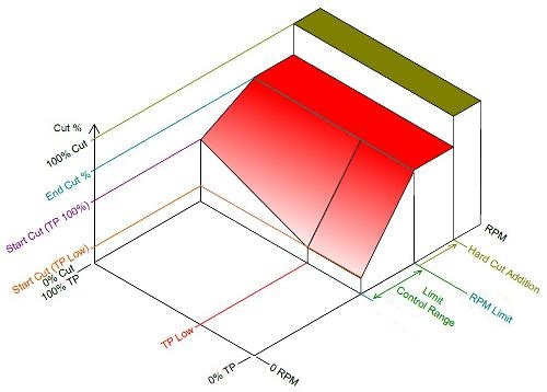
The diagram below demonstrates limiting operation. The vertical axis shows the percentage cut where 0% (bottom) is no limiting and 100% (top) is full limiting. The bottom right axis is the value being limited. The bottom left axis is throttle position. When the value being limited is within the limit control range (denoted by the sloped red area) the amount of cut will depend on throttle position. If the value being limited exceeds the end of the limit control range, then a hard limit can be applied (green area).
It is highly recommended to print this diagram and write your settings on it to better gain an understanding of the limiting system while trying to configure it.
Warning: Advanced mode limiting settings should only be adjusted by experienced tuners. Make sure you understand EXACTLY what a setting does before altering it.
Enables custom control over the cut percentages and effects. With advanced mode turned to OFF the ECU will force these custom settings to generic numbers.
This setting selects whether a hard cut will be implemented at the point specified by the Hard Limit Activation. The following options are available: ·OFF - hard cutting is turned off. ·Ign 100% Cut - the hard cut is ignition only. ·Fuel 100% Cut - the hard cut is fuel only. ·Fuel & Ign 100% Cut - the hard cut is both fuel and ignition.
The cut effect specifies the type of cutting sequence. ·Adaptive - The cutting sequence is randomized to avoid the same cylinder being cut too many times consecutively (Typical Setting) ·Constant - The cutting sequence is fixed for a particular percentage cut.
Specifies the range that the limiting operates over, the Limit control range operates under the specified limit value. For example, with an RPM limit set to 7000 and a control range of 200, the limit would operate between 6800 and 7000 RPM. A typical RPM Limit Control Range would be 200 RPM.
Specifies how far past the end of the Limit Control Range you can go before the hard limit will apply. A typical value for an RPM Limit would be 200 RPM.
Specifies the throttle position below which the Start Cut (TP Low) cut value applies. Above this throttle position the cut level is determined by a linear gradient between the Start Cut (TP Low) value and the Start Cut (TP 100) value. A typical value would be 15%.
Specifies the percentage cut at the end of the Limit Control Range. A typical value would be 90%.
Specifies the percentage cut at the start of the Limit Control Range with 100% throttle. A typical value would be 60%. A TPS(Main) value between 100% and the TPS Low value will result in a cut value that is between Start Cut (TPS Low) &
Specifies the percentage cut at the start of the Limit Control Range when TPS(Main) is below the TPS Low value. A typical value would be 30%.
Note: If Start Cut (TPS Low) is set above Start Cut (TPS 100) the higher cut value will be used.
Specifies the time it will take to remove the cut in ms, 500ms would be a typical value.
Specifies the amount of ignition trim applied when limiting system is active. A typical value would be -5 degrees.
Specifies the amount of fuel trim applied when limiting system is active. A typical value would be 0%. Note: Limit Fuel Trim is only visible when the Limit Mode is set to Ignition %Cut (or Disabled).
Specifies the time it will take to remove the fuel and ignition trim in ms, 500ms would be a typical value.
|
Application Notes:
When setting up a limit, ideally you want it to be as smooth and as stable as possible. You will be able to tell when a limit is smooth as the percentage cut will stabilize. Here are tips for setting up a smooth limit:
·For a smooth limit you want the limit to settle within the limit control range.
·An engine will settle into a position within the control range easier with a softer cut gradient.
·Increase the Limit Control Range for given % cut parameters to decrease the control range gradient.
·Bring the start and end cuts together to decrease the control range gradient.
·If you find when you hit the limit at full throttle, the limit is overshot then settled into, increase the Start Cut (TP 100).
Notes on using Launch Control
Note: The more retard that is added, the more boost that will be generated (to an extent) but the more heat that will be generated. Setting this value incorrectly could result in engine damage and should only be adjusted by experienced tuners.
Note: A typical value for Launch Ignition Trim is one that gives about 20 degrees ATDC.
Note: A typical value for Ign Trim Activation (TP) is 85%
Note: The following points should be observed when setting up Launch Control:
·Obviously it is better to start with the RPM limit too low for a given vehicle speed and raise it.
·The Launch Ign Trim should be set to 0 for all non-turbo applications or where retard is not required.
Note: The state of the Launch Control system can be verified under the Motorsport tab of the Runtime Values window (F12 key).