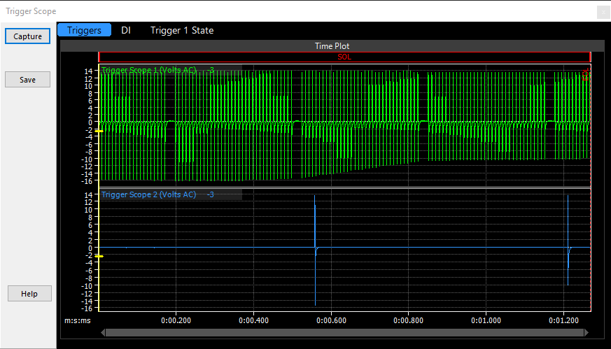
Note: G4X Atom and Monsoon ECUs pre V3.0 only have a digital trigger scope due to hardware differences.
The Trigger Scope function is designed to assist in analysing the signals on Trigger 1 and Trigger 2 pins.This is helpful for:
·Determining the correct arming voltage settings
·Ensuring that the correct trigger pattern has been selected
·Providing feedback to technical support staff for diagnostics
The Trigger Scope is only available on selected Link ECUs.
NOTE: The Trigger Scope is only a basic oscilloscope with limited measuring precision. It is designed to give a quick indication of the presence and quality of trigger signals. A high quality purpose built oscilloscope should be used if more accurate measurements are required.
The Trigger Scope uses digital sampling technology to take high speed samples of the signals.

Trigger Scope Form
The following functions are provided for operating the Trigger Scope:
·Capture - Starts a sample, download and display sequence.
·Save - Saves the data to a log file.
·Help - Opens this help page.
·Triggers, DI and Trigger 1 State Tabs to show the basic trigger signals, VVT Signals and trigger decoding state respectively.
Tips for Trigger Scope use
·Trigger Scope is going to try and capture a minimum of 720° (degrees) of crank revolution, the total period captured will depend upon the RPM the ECU is reading.
·When using Trigger Scope it is necessary to setup some fields in the Trigger Setup before using trigger scope. Fields to setup before hand include Trigger Type, Trigger Position and Trigger Pull-ups. If the ECU is displaying inaccurate RPM information the Trigger Scope will not work correctly.
·The sample the Trigger Scope captures is started from when the Capture button is clicked.
AC and DC Coupling
·The Trigger Scope uses AC coupling when the trigger channel is set to Reluctor. This means that in the unusual case where there is a DC offset in the trigger signal due to a wiring error it may not be visible on the Trigger Scope.
·The Trigger Scope uses DC coupling when the trigger channel is set to Optical/Hall.
Using the Trigger Scope Set Arming Voltages
For reluctor type trigger signals the Trigger scope can be used to determine the correct arming voltage. The procedure to find the correct arming voltage at a particular RPM is as follows:
1.Run the engine at the desired RPM.
2.Click Capture to take a trigger sample. The trigger scope will automatically set the V/Div and Time/Div for the appropriate sensor type and engine speed.
3.Find the smallest height pulse on the trigger 1 or 2 signal.
4.Zoom in on the smallest pulse.
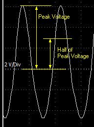
5.Measure the peak amplitude above zero volts of the signal as in the picture below. Use the V/Div number to count determine the peak voltage. In the diagram below the Peak voltage is three divisions at 2V per division. The peak voltage is 6 Volts.
6.The required arming voltage is half the peak voltage. So in the diagram, the correct arming voltage is 3 Volts.

Setting Arming Voltage From the Trigger Scope
Note: ECU Logging is Paused while the Trigger Scope form is open.


